Do you have a question about the Sungrow SG8.0RT and is the answer not in the manual?
Details about trademarks owned by SUNGROW and other registered trademarks.
Prohibitions regarding the use of SUNGROW firmware or software.
Specifies the models of low-power grid-connected PV string inverters this manual is valid for.
Identifies the intended audience for this manual, including professional technicians.
Explains important safety symbols used in the manual to ensure safety.
Check safety signs, labels, nameplates, and product appearance after receiving.
Ensure no electrical connection before installation; avoid wall wiring.
Handle high voltage safely, use insulated tools, and ensure proper grounding.
Avoid touching enclosure or hot parts; do not plug/unplug connectors while operating.
Disconnect power before maintenance; measure voltage after power-off.
Scrap the product according to local regulations to avoid losses.
Inverter converts DC to grid-compatible AC power for the utility grid.
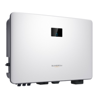
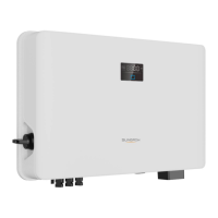
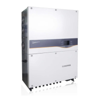
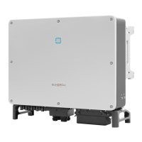
Details the model description, appearance, and dimensions of the inverter.
Explains various symbols found on the product and their meanings.
Describes the meaning of different LED colors and states for inverter status.
Shows the main circuit diagram of the inverter for technical understanding.
Outlines basic functions like conversion, data storage, parameter configuration.
Describes the auto-test procedure for grid connection in Italy.
Explains AFCI activation, self-test, and alarm clearing for fault detection.
Details SPI interface for choosing grid protection modes based on local requirements.
Lists functions like Module-level MPPT, shutdown, monitoring, and IV curve diagnosis.
Inspect the product for damage and check delivery scope after receiving.
Store inverter in original packing case under specified temperature and humidity.
Ensure no electrical connection; avoid wall wiring; use proper handling.
Install in a sheltered, well-ventilated area, free from flammable materials.
Specifies environmental conditions for installation, including temperature and humidity.
Mounting structure must be solid and comply with local standards.
Install the inverter vertically, not horizontally or tilted.
Ensure sufficient clearance around the inverter for heat dissipation.
Lists recommended tools for installation, including safety gear.
Handle the inverter carefully, be aware of its weight, and use handles.
Install the inverter on the wall using a wall-mounting bracket and expansion plug sets.
Shows how to clamp the optimizer parallel to the back of the PV module by clips.
Handle high voltage with PPE; ensure cables are voltage-free before connections.
Identifies and describes the function of various terminals on the inverter.
Provides a general overview of the electrical connections for the inverter.
Details how to connect the external protective grounding cable reliably.
Specifies cross-sectional areas for grounding cables and general grounding requirements.
Step-by-step guide to prepare and connect the grounding cable.
Details requirements for connecting AC cables to the inverter.
Install AC circuit breaker; ensure grid voltage/frequency compliance.
Step-by-step guide to assemble the AC connector for inverters under 15 kW.
Connects the assembled AC connector to the inverter's AC terminal.
Step-by-step guide to assemble the AC connector for inverters 15 kW and above.
Connects the assembled AC connector (≥ 15 kW) to the inverter's AC terminal.
Safety precautions and procedures for connecting DC cables to the inverter.
Details the number of PV inputs and string configuration requirements.
Step-by-step guide to assemble MC4 or MC4-Evo2 connectors for PV cables.
Connects PV connectors to the inverter's terminals and checks polarity.
Connects communication modules for Ethernet or WLAN.
Steps to connect the WiNet-S/WiNet-S2 module for Ethernet communication.
Steps to install the WiNet-S/WiNet-S2 module for WLAN communication.
Steps to install the WiFi module for connection in Brazil.
Connects the Smart Energy Meter for feed-in power function.
Step-by-step guide to assemble the COM connector for meter connection.
Installs the assembled COM connector into the COM2 terminal.
Explains RS485 connection for device or inverter-to-inverter communication.
Details the RS485 system and daisy chain connection for multiple inverters.
Step-by-step guide to assemble the COM connector for RS485 connection.
Installs the assembled COM connector into the COM2 terminal for RS485.
Connects the DO relay for earth fault alarm with external indicator or buzzer.
Connects the inverter to an external DRED for demand response modes.
Connects the inverter to a Ripple Control Receiver for grid dispatching signals.
Details NS Protection terminals for emergency stop functions.
Check installation, switches, and connections before starting the inverter.
Safely power on the inverter by closing AC breaker, DC switch, and external DC switch.
Install iSolarCloud App, register account, and download firmware package.
Create a plant in iSolarCloud App by filling in details like name, type, and location.
Check optimizer installation and attach QR code labels to the physical layout.
Overview of iSolarCloud App for monitoring, data logging, and maintenance.
Instructions for downloading and installing the iSolarCloud App via app stores or QR code.
Process for registering end-user or distributor/installer accounts in the app.
Requirements and procedure for logging into the iSolarCloud App.
Guide to setting Country/Region and other initial parameters for the inverter.
Overview of parameter viewing and setting functions available in the app.
Describes the inverter state and energy flow chart shown on the app's home screen.
View detailed running information like PV voltage, current, and inverter status.
Access event records, fault alarms, and power generation charts within the app.
View detailed fault information, including occurrence time and alarm level.
Browse historical event records, such as standby status changes.
Access settings for parameters, firmware updates, and device information.
Configure system parameters like boot/shutdown, date/time, and software version.
Set running time parameters and PID parameters for inverter operation.
Configure NS protection settings for emergency stop functions.
Set AFCI parameters for arc fault detection.
Configure active power regulation parameters like soft start and gradient control.
Set feed-in power limitations and zero-export per phase.
Configure reactive power regulation modes (Off, PF, Qt, Q(P), Q(U)).
Set device address for communication parameters.
Steps to download and update the inverter firmware via the app.
Perform and download auto-test reports for grid code compliance.
Configure SPI parameters for Italian grid code compliance.
Safely disconnect the inverter from AC and DC power sources before maintenance.
Steps to dismantle the inverter, ensuring safety from burns and electric shock.
Dispose of the inverter according to local regulations for electronic waste.
Table of fault codes, names, and corrective measures for inverter issues.
General guidelines and notices for performing maintenance on the inverter.
Safety notices for maintenance, including using insulation tools and disconnecting power.
Perform a quick shutdown by turning off AC breaker or connecting RSD-1/RSD-2.
Schedule for device cleaning, cable checks, and general system status checks.
Procedures for cleaning or replacing inverter fans, ensuring power is off.
Technical specifications for various inverter models including power, voltage, and current.
Details warranty service for product faults and replacement policies.
Information needed to contact SUNGROW for product support.