19
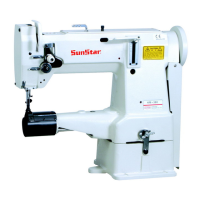
12) Adjusting the feed cam
As shown in Figure 25, turn the pulley by hand to lower the end of the feed dog ①. When it aligns with the upper side of the
needle plate ②, adjust the upper end of the needle hole of the needle ③ to align with the upper side of the needle plate ②. Also at
this point, the upper shaft carved line ④ and the carved dot ⑤ of the feed cam “A”will come in alignment with “K”as shown in
Figure 25. Afterwards, adjust the feed cam “A”and “C”by bringing the carved dot ⑦ of the feed cam “C”and the upper shaft
carved line ⑧ in alignment with “D”. At this point (when the standard feed cam adjustment is complete), the center of no. 2 screw
⑥ of the feed cam “A”and the center of no. 1 screw ⑨ of the feed cam “C”will have come in alignment. Depending on the type
of sewing materials, however, the center of no. 2 screw ⑥ and that of no. 1 screw could be slightly off from a straight line.
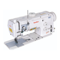
[ Figure 26 ]
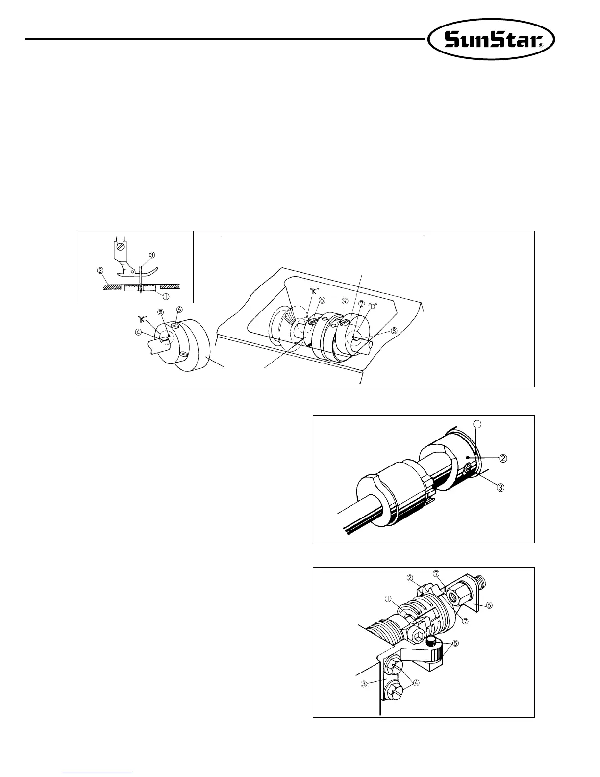
[ Figure 27 ]
13)
Timing adjustment of trimming devices
A. Turn the pulley by hand to bring the needle bar
accurately to its lowest point. Bring the carved dot ①
of the lower shaft middle bushing in the bed, with the
location dot ② of the trimming cam. Tighten with
two fixing screws ③. (Refer to Figure 26)
B. Fixing the “B”position of trimming drive gear
a)
As shown in Figure 27, check how the trimming drive
gear “B”② is inserted into the stopper lever ①.
b) With the stopper lever ① pressed against the
stopper rubber ⑤ of the stopper ③, loosen two
fixing screws ④.
c) Move the trimming drive gear “B”② , and adjust
the stopper ③ up and down in order to align the
thread release drive lever ⑥ with the carved line
⑦ of the trimming drive gear “B”. Tighten two
fixing screws ④ firmly while the baselines are
aligned with each other.
[ Figure 25 ]
Feed cam “A”
Feed cam “C”