22
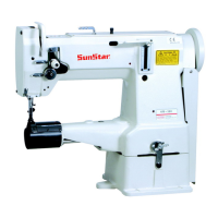
[ Figure 37 ]
Bobbin catcher-adjusting line
Fixed blade
Movable blade
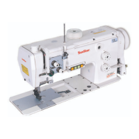
17) Adjusting the bobbin catcher
A. Adjusting the bobbin catcher lever
With the bobbin catcher lever ③ not in motion,
unfasten the lever screw ⑥ to bring the tip of the
bobbin catcher lever ③ against the end of the
connecting link ② as shown with ⓐ in Figure 38.
B. Run the trimming function manually. As the movable
blade moves forward and the end tip of the fixed blade
comes to align with the bobbin catcher-adjusting line as
shown in Figure 37, stop the machine. At this point,
unfasten the bobbin catcher screw ⑤ so that the contact
surface of the bobbin catcher ④ touches smoothly with
the middle of the projecting part of the bobbin ①. See
if the bobbin catcher returns smoothly after trimming.
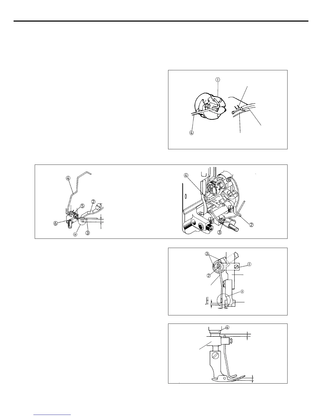
[ Figure 39 ]
Presser bar
Presser foot
Wiper
2mm
[ Figure 40 ]
Wiper holder
1mm
13.5mm
18) Adjusting the wiper
As shown in Figure 39, loosen the wiper holder screw ①
to bring ⓐ in parallel with the left surface of the presser
foot. Assemble so that the lower side of the presser bar
bushing ④ is 13.5mm apart from the upper side of the
wiper holder as shown in Figure 40. Manually run the
wiper, and set a clearance between the lower side of the
wiper and the gap in the upper side of the presser foot at
1mm. Fix with the screw ②.
By using two wiper shaft screws ③, set a clearance of
2mm between the right side of the wiper and the left side
of the presser foot when the wiper is not in motion.
Tighten with screws after adjustments.
[ Figure 38 ]
2mm