24 25
Port Function NO. Denition
Port 1
1.Only Anti-reverse version with this port.
2.Connect external CT to realize the anti-reverse
function of Sunways STS series inverter.
1
Connect S1 cable (Black CT) or white
black cable (Blue CT)
2
Connect S2 cable (Black CT) or black
cable (Blue CT)
3 NULL
Port 1
1.Anti-reverse/RS485/DRED version with this
port.
2.In case of multiple inverters, all the inverters
can be connected via RS485 cables in the daisy
chain manner to realize the communication.
1 RS485 A
2 RS485 B
3 PE/NULL
Port 2
1.Only DRED version with this port.
2.DRED means demand response enable device.
The AS/NZS 4777.2:2015 requires inverters to
support demand response mode (DRM). This
function is for inverter that comply with AS/
NZS4777.2:2015 standard.
3.Sunways inverter is fully complied with all
DRM. The 6pin connector is used for DRM
connection.
4.Support DRM command: DRM0, DRM5, DRM6,
DRM7, DRM8.
1 COM/DRMO
2 REFGEN
3 DRM4/8
4 DRM3/7
5 DRM2/6
6 DRM1/5
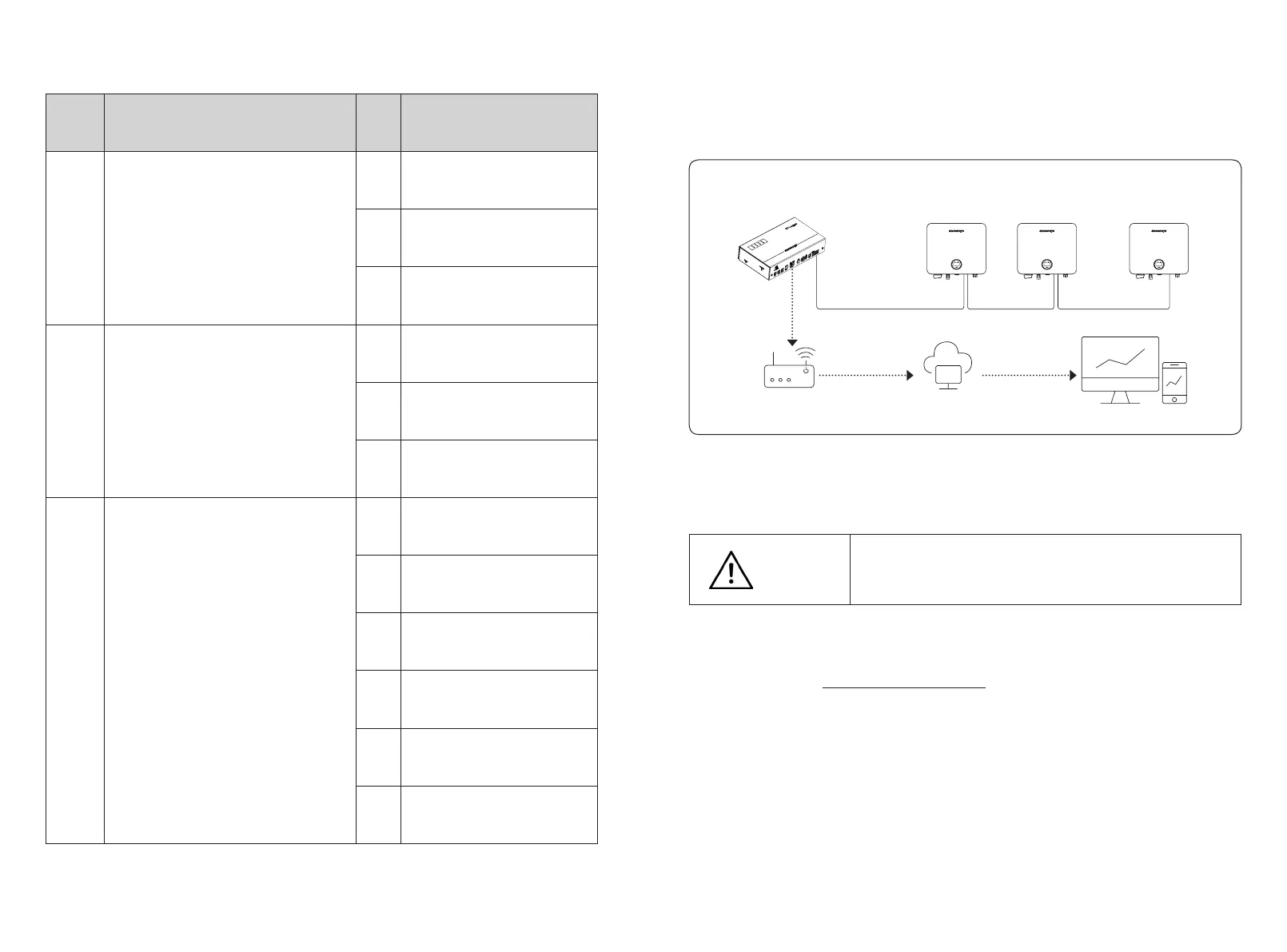
4.5.2 RS485 Communication
STS series single-phase inverter supports multiple inverters connection to a data logger in a
daisy chain manner through RS485 protocol.
Multiple inverters connection diagram as shown in Figure 4-21:
Dierent versions of the inverter have dierent terminals, which are dened as below:
4.5.3 Anti-reverse or power limit solution
Anti-reverse or power limit solution, wiring instructions and configuration, please contact
Sunways after-sales at service@sunways-tech.com.
4.5.4 Connection steps:
1) Remove the CT/DRED plate in the bottom of the inverter with a cross screwdriver.
2) Put the cables which you need through the components in the following order: screw cap,
sealing ring, insulator, metal plate, nut and 3/6pin connector, as shown in Figure 4-22:
3) Insert the cable to the port in the 3/6pin connector and fasten with a screwdriver.
4) Insert the 3/6pin connector into the 3/6pin connecter inside the inverter, and screw the CT/
DRED plate back with a cross screwdriver, as shown in Figure 4-23:
The maximum distance between the inverter at the end of the daisy chain and the Data logger
should be within 1000M.
STS 1~3.3KTL
series inverter
STS 1~3.3KTL
series inverter
STS 1~3.3KTL
series inverter
Data logger
Sunways server
Internet
RS485 RS485 RS485
Internet
Figure 4-21
Suggest using the RS485 communication cable with a cross-sectional area
of 0.75-1.5mm² and an outer diameter of 5mm-10mm.
RS485 cable requirements: Shielded twisted-pair cable or shielded twisted
Ethernet cable.
Attention
...