26 27
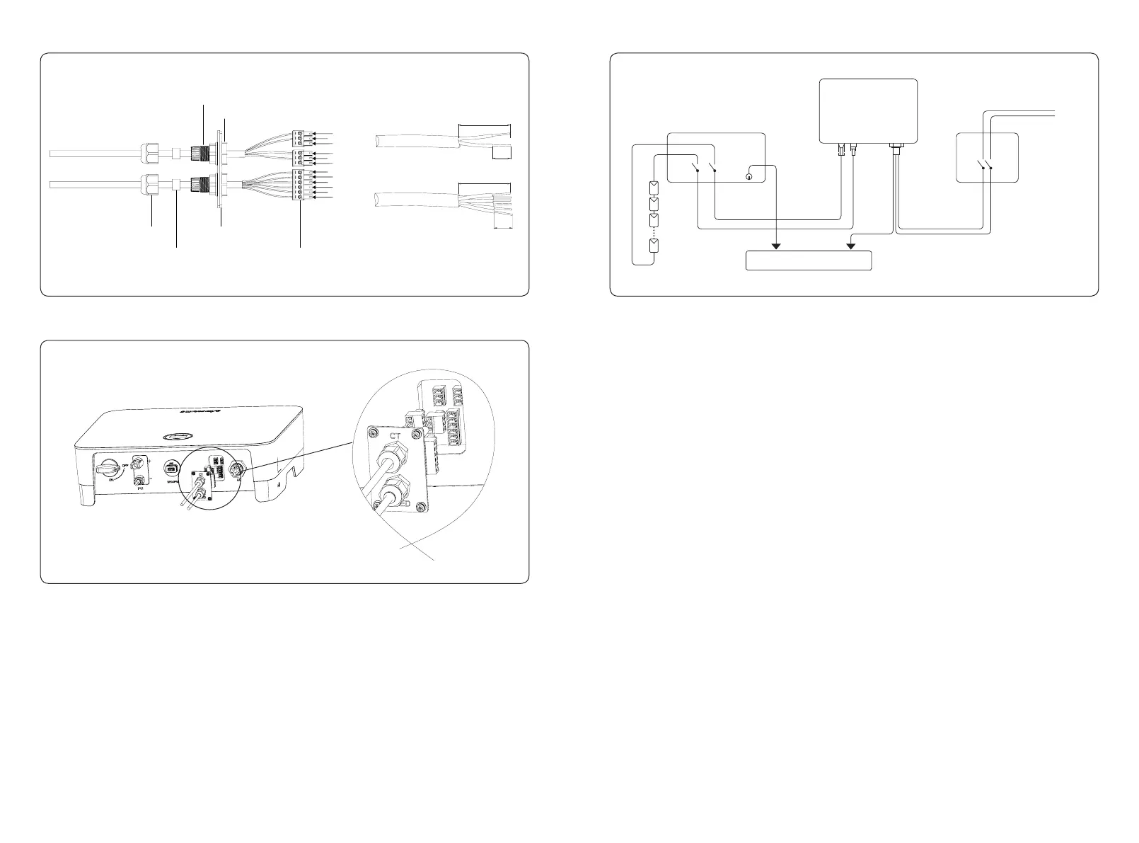
Figure 4-22
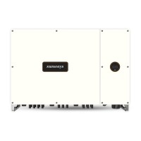
Figure 4-23
4.6 System Layout of Units without Integrated DC Switch
Local standards or codes may require that PV systems are tted with an external DC switch on
the DC side. The DC switch must be able to safely disconnect the open-circuit voltage of the PV
array plus a safety reserve of 20%. Install a DC switch to each PV string to isolate the DC side of
the inverter. We recommend the following electrical connection, as shown in Figure 4-24:
Figure 4-24
5. Start and Stop
5.1 Start the Inverter
When starting the inverter, follow these steps:
1) Turn on the AC breaker rst (close the AC circuit breaker).
2) Turn on the DC switch in the bottom. If the PV string voltage higher than the inverter start-up
voltage, the inverter will start.
3) When both AC and DC power supply are normal, the inverter is ready to start. The inverter
will initiate from checking its internal parameters and grid parameters, if it’s within the range,
the green light on the left side of the screen begins to ash, and the “Waiting” message will be
displayed on the OLED display.
4) After self-checking completed, the inverter will start generating electricity, the green light
will remain on, and the OLED display will display real-time power information.
5.2 Stop the Inverter
When turning o the inverter, please follow the steps below:
1) Turn o the AC breaker rst.
2) Wait 30 seconds and then turn the DC switch to the “OFF” position. At this time, there is
remaining power in the inverter capacitor. Wait for 5 minutes until the inverter is completely
de-energized before operating.
3) Disconnect the AC and DC cables.
DC Switch
Inverter
PE L
N
To grounding electrode
-
-
+
+
Grid
AC Breaker
DC INPUT AC OUTPUT
20-25mm
1
3
3
1
2
4
6
2
2
1
3
5
Port 1
Port 2
Port 3
6mm
6mm
20-25mm
Screw cap
Sealing ring
Insulator ring
Metal plate
3/6pin connector
Nut