5V
5V
ZD2
Tr2
Tr1
ZD1
D
Sensor circuit
+
–
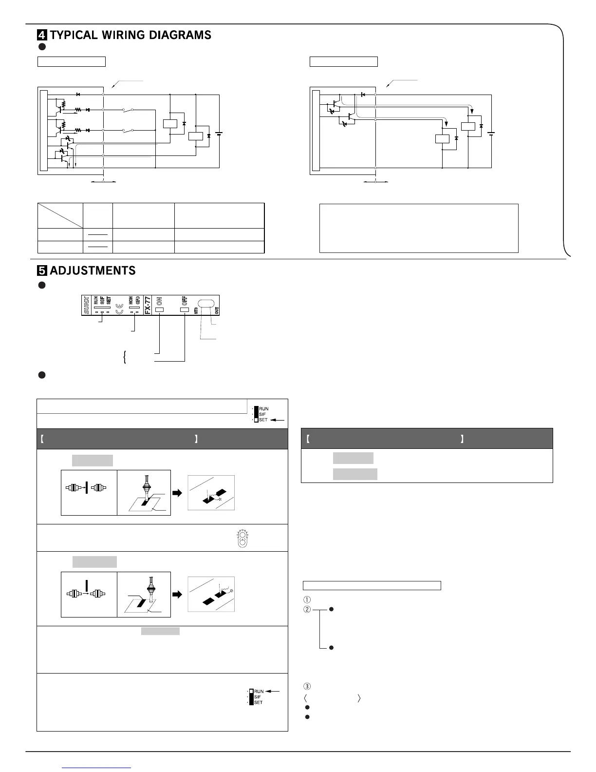
12 to 24V DC
± 10%
(Brown) +V
Color code
(Black) Sensing output
(Blue) 0V
(Orange) Self-diagnosis
output
Internal circuit Users' circuit
(Pink) Input 1
Load
Load
100mA
max.
50mA
max.
(Violet) Input 2
NPN output type
ZD2
Tr3
Tr4
ZD1
+
–
Sensor circuit
(Black) Sensing output
(Blue) 0V
Internal circuit Users' circuit
(Orange)
Self-diagnosis output
Load
Load
D
100mA max.
50mA
max.
PNP output type
12 to 24V DC
± 10%
(Brown) +V
Color code
Model No.
External synchronization input (ES)
Remote sensitivity setting OFF input (R.OFF)
Remote sensitivity setting ON input (R.ON)
Input 1
Input 2
FX-7(P)
FX-7G(P)
FX-75
FX-75G
FX-77
FX-77G
Emission disable input (CONT.)
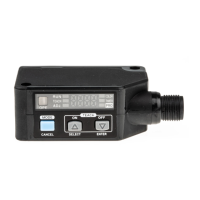
Input
Mode selection switch
Timer operation
selection switch (Note)
Sensitivity setting button
ON button
OFF button
Operation
indicator (Red)
Stability
indicator (Green)
Mark
Base
Light
interrupted
condition
Thru-beam type
Reflective
type
Thru-beam type
Reflective
type
STB
OUT
Mark
Base
1. Place the fiber cable within the sensing range. (Note 1)
2. Set the mode selection switch to ‘SET’
3. Press ON button with the object present.
When ON state is recognized by the sensor,
stability indicator (green) will flash.
6.
Press ON button with object absent.
Press OFF button with object present.
5. Press OFF button with the object absent.
4.
For sensing output ON with object present
Light is
received
condition
7.
For sensing output ON with object absent
ON
OFF
ON
OFF
The stability indicator will flash twice if the sensitivity gap between
ON state and OFF state is sufficient and a stable detection is
possible.
The stablility indicator will flash continuously if stable detection
is not
possible. (Note 2)
Set the mode selection switch to ‘RUN’.
The sensitivity setting buttons become
ineffective. So, even if the buttons are pressed
by mistake , the registered sensitivity will remain
unchanged.
I/O circuit diagrams
Note: The designation of input wires differ depending on the model.
Note: Synchronization selection switch for FX-75, FX-75G.
Use of sensitivity setting buttons
(Common for all models)
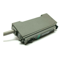
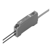
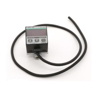
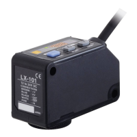
Part description
Refer to the catalog as the sensing range differs according to the type of fiber
cable. The sensing range of the reflective type fiber cable is the value for
white non-glossy paper. The actual sensing distance differs according to the
color of the sensing object, its surface condition, etc.
The sensitivity can also be set under unstable sensing condition. But the
severe condition may affect the sensing.
The set sensitivity is stored in an EEPROM. Since the EEPROM has a
lifetime, the sensitivity setting cannot be done for more than 100,000 times.
Do not move or bend the fiber cable after the sensitivity setting. Detection
may become unstable.
Symbols ... D: Reverse supply polarity protection diode
ZD1, ZD2: Surge absorption zener diode
Tr1, Tr2: NPN output transistor
Tr3, Tr4: PNP output transistor
Set the mode selection switch to ‘SET’.
In case of Light-ON operation
In the dark condition, press the ON button and then the OFF button
successively. (or, make the remote sensitivity setting ON input and
then the OFF input Low successively.)
In case of Light-OFF operation
In the dark condition, press the OFF button and then the ON button
successively. (or, make the remote sensitivity setting OFF input and
then the ON input Low successively.)
Set the mode selection switch to ‘RUN’.
Applications
For getting a long sensing range with reflective type sensor.
For using thru-beam type sensor in an unfavorable sensing environment.
How to set the maximum sensitivity
Notes: 1)
2)
3)
4)
 Loading...