T
T T T
Timer
operation
selection
switch
Output operation
Sensing
state
NON
OFD
NON
OFD
NormalTimer
ON in sensing
state
ON in non-
sensing state
ON in sensing
state
ON in non-
sensing state
Sensing
ON
Non-
sensing
OFF
ON
OFF
ON
OFF
ON
OFF
Timer period T=40ms approx.
Orange (Self-diagnosis output)
Black (Sensing output)
Brown (+V)
Blue (0V)
Orange (Self-diagnosis output)
Black (Sensing output)
Brown (+V)
Blue (0V)
Pink
Violet
ON
OFF
ON
OFF
Remote sens.
setting ON input
Remote sens.
setting OFF input
Pink
Violet
Remote sens.
setting ON input
Remote sens.
setting OFF input
State
High
Low
Signal condition
4.5 to 30V or open
0 to 1V
No. of blinks
Relation with
the stability
indicator
Margin
STB
OUT
Lights
off
Lights on
012345
STB
OUT
Low High
Step Operation
1.
2.
3.
4.
5.
6.
7.
Set the mode selection switch to ‘SET’.
Press ‘ON’ button.
(The stability indicator will blink twice.)
[Response time: 0.5ms or less (Note)]
Set the mode selection switch to ‘RUN’.
(This completes the setting for one sensor.)
Apply steps 1 and 2 for the second sensor.
Press ‘OFF’ button.
(The stability indicator will blink twice.)
[Response time: 0.7ms or less (Note)]
Set the mode selection switch to ‘RUN’
(This completes the setting.)
RUN
SET
SIF
RUN
SET
SIF
Step Operation
1.
2.
Button Emitting frequency Response time
ON
OFF
FREQ.1
0.5ms or less
0.7ms or less
BROWN , +V
BLUE , 0V
PINK , R.ON
FREQ.1
BLACK , OUT
ORANGE , ALM
VIOLET , R.OFF
FREQ.2
FREQ.2
BROWN , +V
BLUE , 0V
PINK , R.ON
FREQ.1
BLACK , OUT
ORANGE , ALM
VIOLET , R.OFF
FREQ.2
RUN
SET
SIF
Press ‘ON’ and ‘OFF’ buttons simultaneously again.
(The stability indicator will flash twice.)
How to set
How to cancel
ON
OFF
ON
OFF
ON
OFF
ON
OFF
Press ‘ON’ and ‘OFF’ buttons
simultaneously for minimum two
seconds continuously. The stability
indicator (green) will blink.
Press ‘ON’ and ‘OFF’ buttons
simultaneously for minimum two
seconds continuously. The stability
indicator (green) will blink.
A mark can be put on the nameplate on the side of the sensor
body for identification. Please use this, when required.
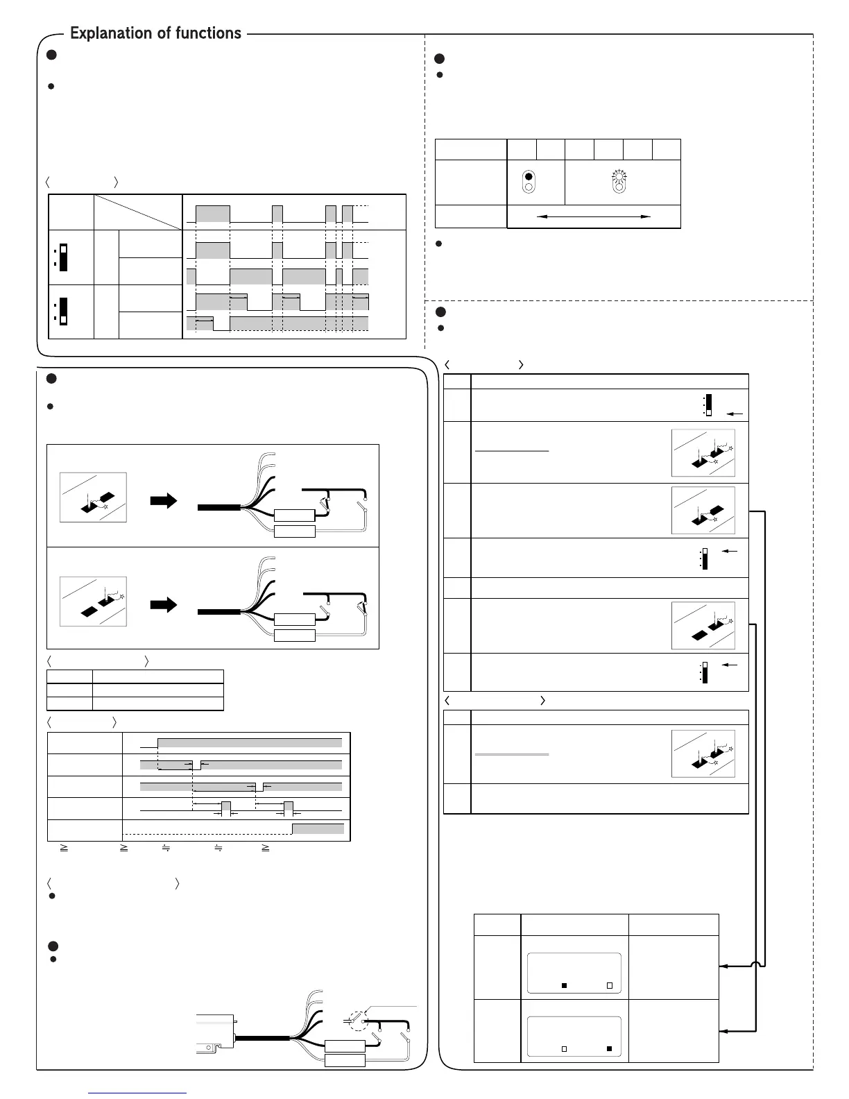
Off-delay timer function
(For standard and remote sensitivity setting types only)
Standard and remote sensitivity setting types have an approx. 40ms
fixed off-delay timer. The timer works when the timer operation
selection switch is set to ‘OFD’. The output is extended for a certain
period of time, and is useful when the response time of the connect-
ing device is slow or when the sensing signal from a tiny object is
too short.
Time chart
Use of remote sensitivity setting input
(For FX-77, FX-77G only)
Basically, the method is similar to that described in ‘Use of sensitivity
setting buttons’. However, instead of pressing the sensitivity setting
buttons, make the remote sensitivity setting inputs Low.
Answer back function
The self-diagnosis output turns ON for approx. 40ms when ON input or OFF
input is accepted by the sensor. (This output does not turn ON if there is no
sensitivity difference between ON input and OFF input and stable sensing is
not achieved.)
Cancelling the setting made by remote sensitivity setting inputs
Time chart
Sensitivity margin indicating function (Incorporated in all models)
After setting the sensitivity, the margin of the sensitivity can be
visually confirmed. The sensitivity margin can be confirmed by the
number of times the stability indicator (green) blinks when the
mode selection switch is changed from ‘SET’ to ‘SIF’ or ‘RUN’.
Normally, the margin should be set as large as possible. (Method of
increasing the margin: shorten the sensing distance, use the
optimum fiber cable, etc.)
Interference prevention function (Incorporated in all models)
The FX-7 series has a built-in interference prevention function. Two fiber cables
can be mounted very closely by setting different emission frequencies.
Power supply
Remote sens. setting
ON input (Low active)
Remote sens. setting
OFF input (Low active)
Sensing output
Sensing possible
T1
T2
T5
T2
T4 T4
T3
(Note) (Note)
T3
ON
OFF
High
Low
High
Low
ON
OFF
T1 1,000ms, T2 5ms, T3 310ms, T4 40ms, T5 500ms
Note:
Self-diagnosis output
(Answer back function)
During period T3, do not change the incident light intensity by
moving the object, etc.
Signal condition
Input impedance: 10kΩ
Sensitivity registered by remote sensitivity setting inputs has a priority over
the manual setting and it cannot be cancelled manually. To cancel the
remote sensitivity setting, arrange one switch at the position
shown in the figure, and
make it open. (The
sensitivity will be locked.)
Turn on the switch for
making sensitivity settings
effective.
Note: When using the interference prevention function, the hysteresis and
the response time increase as compared to that during normal ope-
ration. Always check the operation after setting the interference pre-
vention function.
Orange (Self-diagnosis output)
Black (Sensing output)
Brown (+V)
Blue (0V)
Sensitivity setting
cancellation switch
FX7
Pink
Violet
Remote sens.
setting ON input
Remote sens.
setting OFF input
 Loading...