24
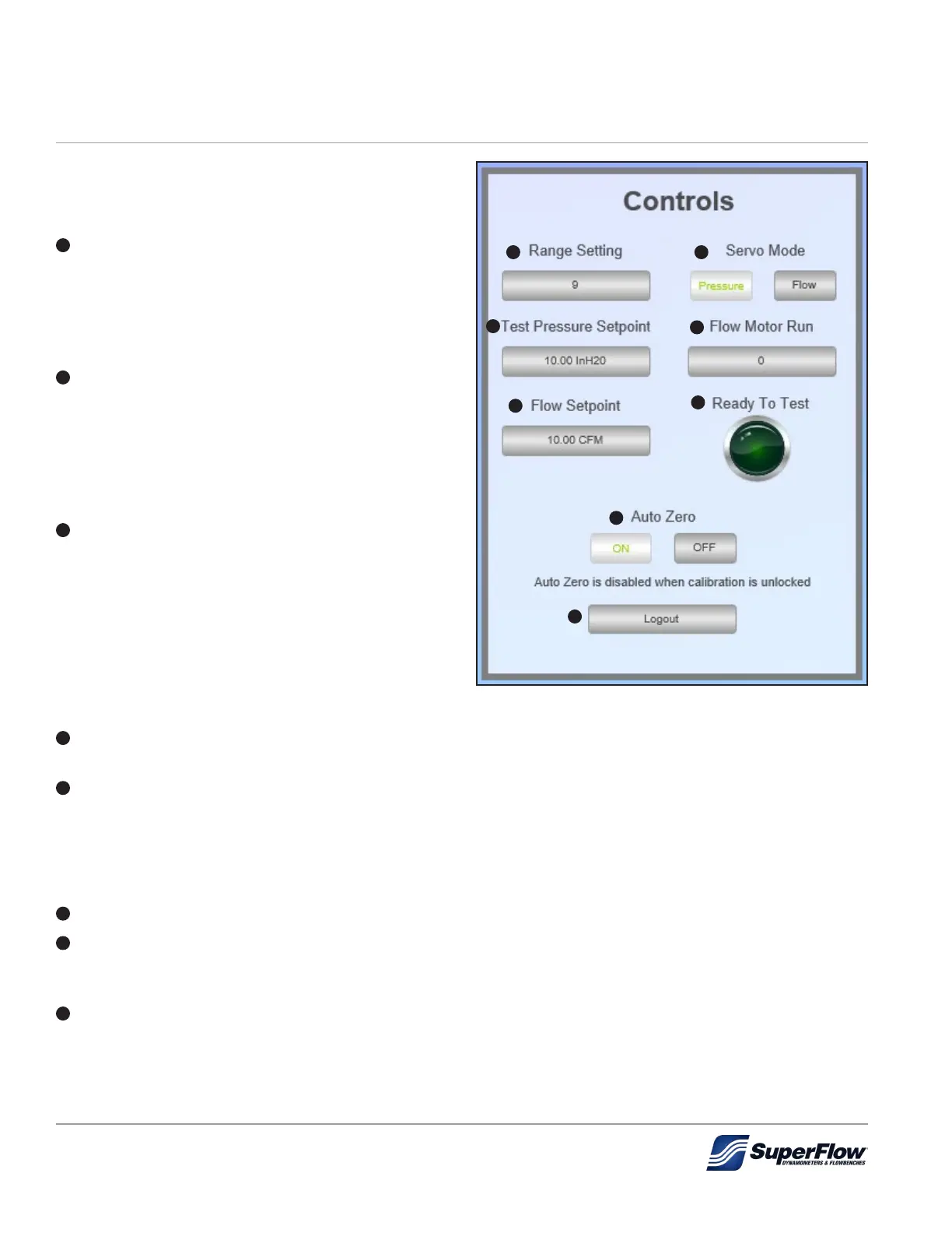
5.2.2.1 Controls Section
The Controls section allows for operational control
of the owbench as described below.
1
Range Setting: Clicking the current range
setting will open a popup window that allows the
operator to enter a new flow range setting (1-10).
The SF-1020i has ten (10) ow ranges (see "Table
5-3. SF-1020i Nominal Flow Ranges" on page
17).
2
Servo Mode: Allows the operator to select
either pressure (selected in Figure 5.6) or ow.
The SF-1020i is capable of controlling the airow
to either test pressure or ow rate. In pressure
mode, the air pressure is set and the ow rate
measured. In ow mode, the airow is set and the
test pressure measured.
3
Test Pressure Setpoint: Clicking the current
test pressure setpoint will open a popup
window that allows the operator to enter a new
test pressure setpoint. If Servo Mode is set
to Pressure, the operator should verify and if
necessary set the test pressure setpoint in the
unit of measurement (InH
2
O) prior to testing.
Example:
10 = A test pressure of 10" H
2
0
4
Flow Motor Run: Clicking the current setting
allows the operator to turn the ow motor ON (1) or OFF (0).
5
Flow Setpoint: Clicking the current ow setpoint will open a popup window that allows the operator to
enter a new ow setpoint. If Servo Mode is set to Flow, the operator should verify and if necessary set
the ow setpoint in the unit of measurement (CFM) prior to testing.
Example:
10 = A ow rate of 10 cfm
6
Ready To Test: This green indicator will illuminate when the ow motor is ON (1).
7
Auto Zero: Allows the operator to select if Auto Zero is ON (selected in Figure 5.6) or OFF. With Auto
Zero ON, the ow bench will ignore small changes in test pressure and ow pressure over
time.
8
Logout: Logs the currently logged in user out and returns them back to the login screen.
Figure 5.6: Controls
1 2
3
4
5
6
7
8
5.0 Operation
 Loading...