Figure
23
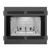
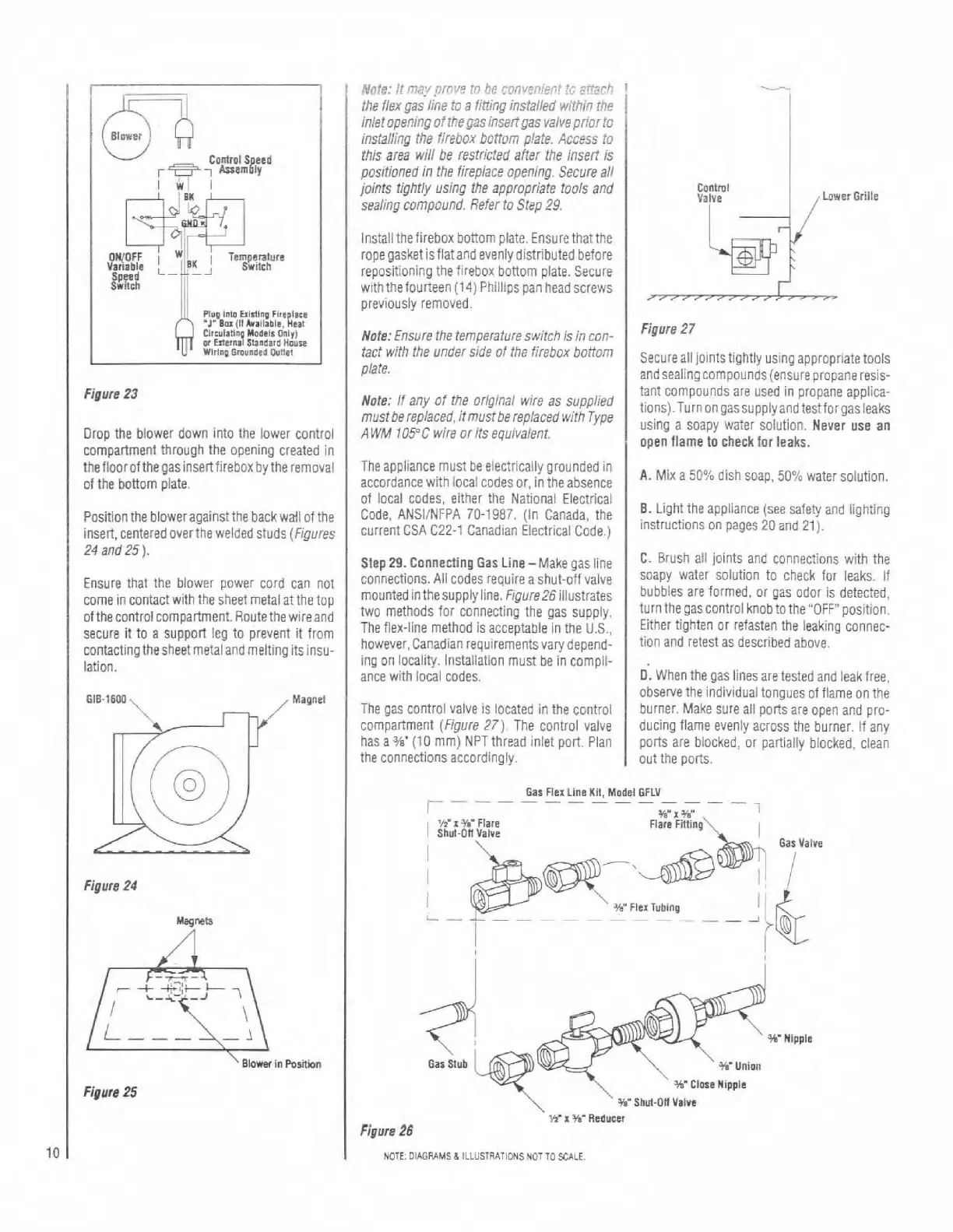
Drop the blower down into the lower control
compartment through the opening created
In
thefloorofthegasinsertfirebox
by
the removal
of the
bonom plate.
Position the bloweragainst the back
wall of the
insert, centered
overthe welded studs (Figures
24
and25).
Ensure that the blower power cord can not
come in contactwith the sheet metal at the top
ofthecontrol compartment. Route the
wireand
secure
it
to a support leg to prevent it from
contactingthesheet
metaland rneiting itsinsu-
lation.
Figure
24
Figure
25
h(l.I.3:
i!
rn??
poi,?
t;,
he
rov>fni.e.;t
ti?
gr?rh
the flex yas line to a fining installed w~thin the
h!etope.?iny ofthe 03s insertgas valvepriortc
instaiiing the firebox bonorn plate. Access to
this area wili be restricted after the
insert is
positioned
in
the fireplace opening. Secure ail
joints
tighty using the appropriate tools and
sealing compound Refer to Step
29.
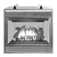
Installthefirebox bottom plate. Ensure thatthe
ropegasket isfiatand evenly distributed before
repositioning the firebox
bonom plate. Secure
with
thefourteen
(14)
Phiilips pan headscrews
previously removed.
Note: Ensure the
temperatureswitch isin con-
tact wlth the under side of the firebox
bottom
piate.
Figure
27
Secure all jOintStiQhtly using appropriate tools
and sealing compounds (ensure propane resis-
T-eapp lace rust
te
e ec:r ta tt~r,!~ncro
,*
acccr~a-ce
hi:n
cca c3t:es
tr,
in rlsansence
I
A.
h'tx a
EC9.>
ckn soap
50';
wi.:e. :ol.r
:I?.
Note:
if
any of the orioinal wire as suppiied
musrbere~laced,itrnustbere~iacedwifh
Type
A
WM
IOS'C
wire or its equivalent.
tant compounds are used in propane
applica-
tions).~urnongassupplyand
testforgasleaks
using
a
soapy
water
solution,
Never
use
an
step
29.
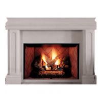
connecting
G~~
~i~~-~~k~
gas
line
C.
Brush 211 joints and connections with the
connections. Ail codes reauire a
sh~~t-nff valve
I
Soapy water solution to check for leaks. If
I
open flame to
check
for leaks.
of local codes, either the National Eiectricai
Code.
ANSIINFPA
70-1987.
(In Canada, the
current
CSA
CZZ-1 Canadian Electrical Code.)
~~
~
~
~~~~~
~7-
-
~
~-
~.
mountedinthesupply line. Figure26lilusfrates
bubbles are formed. or gas odor is detected,
two methods for connecting the gas supply.
tUr"heQasc0ntrol knobtothe"0FF"position.
The flex-line method is acceotabie in the
11s.
Either tighten or refasten the leakinq connec-
0.
Light the appliance (see safety and lighting
i"s"uc'ions on pages
20
and
21).
however, Canad~an re~ulremknts vary depend:
I
tlon and retest as
described
above
ing on locality.
Installation must be
h
cdrnpli-
ance with local codes.
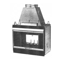
The gas control valve is located in the control
compartment (Figure
27)
The control valve
has a
J/8'
(10
mm) NPT thread inlet port. Plan
the connections accordingly.
D.
When the gas lines are tested and leak free,
observe the Individual tongues of flame on the
burner. Make sure all
pons are open and pro-
ducing
fiarne evenly across the burner. If any
ports are blocked, or partially blocked, clean
out the ports.
Gas
Flex
Line
KII,
Model
GPLV
-
-
-
-
- -
-
-
- - -
-
3b'
Nipple
Gar
Slub
NOTE.
OIAGPAMS
d
ILLUSlRAllONSNOTTOSCALE