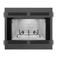
Vent Adagtsr,
no~ble
Walled
Chimney lnslallation
r
Maf3n~
lm!zlla!ion wilhout
a
B!aGe
Carn$-r
Figure
17
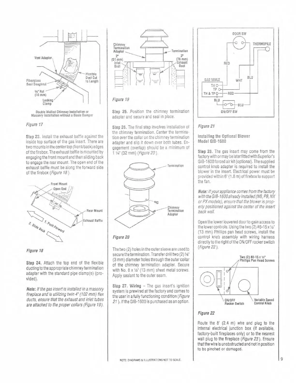
Step
23,
Install the exhaust ba!fle against the
inside top surface of the gas insert. There are
Pa0 mountsinthecentertop (front'back) edges
ofthefirebox.Theexhaust batfie is mounted by
engagingthe frontmountand then siiding back
to engage the rear mount.
Tie open end of the
exhaust baffle must be
aiong the forward side
of the firebox (Figure
18).
Front
Mount
'Elham! Sanle
Step
24.
Attach the top end of the flexible
ducting totheappropriatechimneytermination
adapter with the standard pipe
ciamp(s) (pro-
vided).
Nole: If the gas insert
h
instalied
in
a masonry
fireplace and is utilizing
Win
4"
(102
mm) flex
ducts, ensure that the exhaust and inlet tubes
are attached to the proper collars (Figure
19).
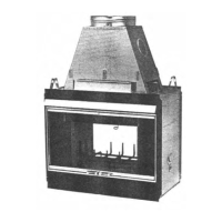
Figure
13
1
Step
25.
Position the chimney termination
OWOFF
sw
adapter and secure aEd seal in place.
1
I
Step
26.
The flnai step involves ins:aliation
of
tile chimney termination. Center the termina-
tion
overthe collar on the chimney :ernination
adapter and siip
8
down
over both tubes. En-
gagement (overlap)
sh9uld
i
'/dm
(32
rnm) (Figure
2C)
a minimum
-1erminaticn
Chimney
Figure
20
Thetwo
121
hole5 inthe outersleeve are used to
securetheiermination.~ransferdrilltwo(2)~/e'
(3
mm) diameterholesthroughthe outer collar
I
ins!a!ling
the
Oplinnzl
E!o',?e?
Model
DIB-1603
Step
28.
The
gas
insert mav come from the
I:c!c-lv:~tncr may :?la'?rt'"flel
u
tnS~p91%'?
"
J
:-1~:Ol:~cec:irVi:Icct.on~li.
'tesdoo~
el
control knob adapter is requireb to instill the
blower in the insert. Electrical oower must be
provided within
6'
(1.8
rn)
offirk~oxtosupoort
the fan.
Nole: l!lou~ 3Dpl3CCP
ccmes
:ror i?e
IJC!OJ~
x.!.?
Ire
S.'B-
l6?23."93P/;rsfa,fed/V3
PE
NY
or PXmodels), ensore that the biokrik pro,o-
eriy pos.?ioned zgainsf the center of the insei!
back
wali.
:I~ri:kf
ON?'
c~v~~r?dd,l~i:niy la;cess!c
tle c#e.ccr!.ols.~s
net-er..vc
,;
?:-15~:.~'
(13 rnm) Pkliiips pan head screws, install the
control
knob assembly with wiring harness
directly to the right
oithe ONiOFFrockerswitch
(F~gure
22)
Two
(2)
18.15
1
W
,f?hillws
Pan
Head
Lrewr
of the chimney termination adapter. Secure
I
with No.
8
x
'h.
113
mm) sheet metal screws.
t
I
Figure
22
Apply sealant to ihe outer seam.
Slep
27.
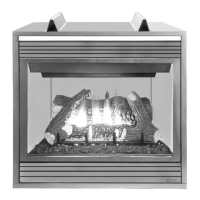
Wiring
-
The gas insen's ignition
system is prewired at the factory and comes to
the user in
afully functioning condition (Figure
21
).
iftheGIB-1EOOispurchasedas
an option.
Route the
8'
(2.4
m) wire and plug to the
internal electrical junction box (if available,
factory-built fireplaces only) or to
the
nearest
wall piug to the fireplace (Figure
23).
Ensure
thatthe wire is
unobstructedandnotinposition
to
bo
pinched
or
dsmagcd.
@.;J
c_i
OWOFF
Vailable
Speed
Rocker Swish
Control
Knob
NOTE
OIMP*MS
5
1LLUSIV.TIONS
NOTTO
SCALE
I