Superiorfireplaces.US.com
126631-01B
8
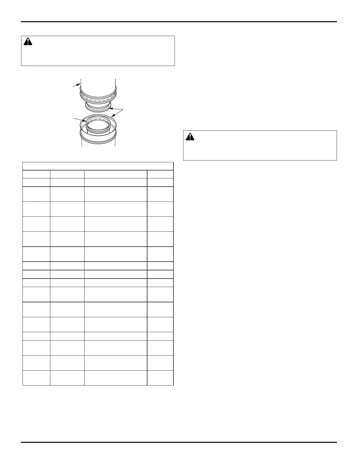
Hemmed
End
8" Stainless
Inner Pipe
12
3
/
8
"
Galvanized
Outer Pipe
WARNING: The opening in collar around chimney
at top of fireplace must not be obstructed. Never use
blown insulation to fill chimney enclosure.
VENTING INSTALLATION Continued
ASSEMBLY AND INSTALLATION OF DOUBLE WALL CHIMNEY
SYSTEM
Eachdoublewallchimneysectionconsistsofagalvanizedouter
pipe, a stainless steel inner flue pipe and a wire spacer. Pipe sections
must be assembled independently as chimney is installed. When
connecting chimney directly to fireplace, inner flue pipe section
mustbeinstalledrstwithlancedsideup.Outerpipesectioncan
then be installed over flue pipe section with hemmed end up. Press
down on each pipe section until lances securely engage hem on
fireplace starter. Wire will assure proper spacing between inner
and outer pipe sections.
Note:ForCanada,usechimneypartsdesignatedHT.
Opening in collar around chimney at top of
fireplace must not be obstructed. Never use blown
insulation to fill chimney enclosure.
Continuetoassemblechimneysectionsasoutlined,makingsure
that both inner and outer pipe sections are locked together. When
installing double wall snap-lock chimney together, it is important to
assurejointbetweenchimneysectionsislocked.Checkbypulling
chimneyupwardafterlocking.Chimneywillnotcomeapartifproperly
locked.Itisnotnecessarytoaddscrewstokeepchimneytogether
(exception-seeFigure11,page9).
TheheightofaverticalchimneypipesupportedONLYbythereplace,
mustnotexceed20feet.Chimneyheightsabove20feetmustbe
supported.
USING ELBOW OFFSETS (30E-8DM)
1. To achieve desired offset, you may install combinations of 12",
18",24",36"and48"lengthofdoublewallpipe(seeoffsetchart,
page9,andFigure9,page8).
Note: For systems with 2 elbow sets, minimum height is 22 feet.
Maximum height for any system is 50 feet.
2. Chimneyweightaboveoffsetrestsonreturnelbow.Strapsmust
besecurelynailedtoraftersorjoists(seeFigure10,detailsAand
B,page8).
3. Maximumlengthofpipebetweensupports(returnelbowor12S-
8DM)is6'ofanglerun.Maximumoftwo6'anglerunsections
perchimneysystem(seeFigure9,page9).
4. Allpipeconnectionsbetweenoffsetandreturnmustbesecured
withtwoscrewsonouterpipeonly(seeFigure11,page10).Do
not penetrate inner stainless.
Figure 8 - Lineal Gain
LINEAL GAIN
CAT. NO. PART NO. DESCRIPTION GAIN
42" Fireplace 37
1
/
2
"
F0895
F0881
12-8DM
12-8HT
Pipe Section 10
5
/
8
"
F0896
F0882
18-8DM
18-8HT
Pipe Section 16
5
/
8
"
F0897
F0883
24-8DM
24-8HT
Pipe Section 23
5
/
8
"
F0898
F0884
36-8DM
36-8HT
Pipe Section 34
5
/
8
"
F0899
F0885
48-8DM
48-8HT
Pipe Section 46
5
/
8
"
F0916 RT-8DM Round Termination 6
7
/
8
"*
RTL-8DM Round Termination 7
3
/
4
"*
F0918 RLT-8DM Round Termination 7
1
/
2
"*
F0917 RTT-8DM
Round Termination with
Slip Section
6
7
/
8
" to
23
1
/
8
"*
RTTL-8DM
Round Termination with
Slip Section
8
1
/
2
" to
21
1
/
2
"*
F0919 RLTT-8DM
Round Termination with
Slip Section
7
1
/
2
" to
21
1
/
4
"*
F0920 ET-8DM SquareChase-Top 12"*
F0922 ETO-8DM
SquareChase-Topwith
Mesh
12"*
F0921 ETL-8DM
SquareChase-Topwith
Slip Section
7" to 15"*
F0923 ETLO-8DM
SquareChase-Topwith
Mesh & Slip Section
12" to
25
1
/
2
"*
* The lineal gain for the terminations is measured to the flue gas
outlet height.