Superiorfireplaces.US.com
126631-01B
7
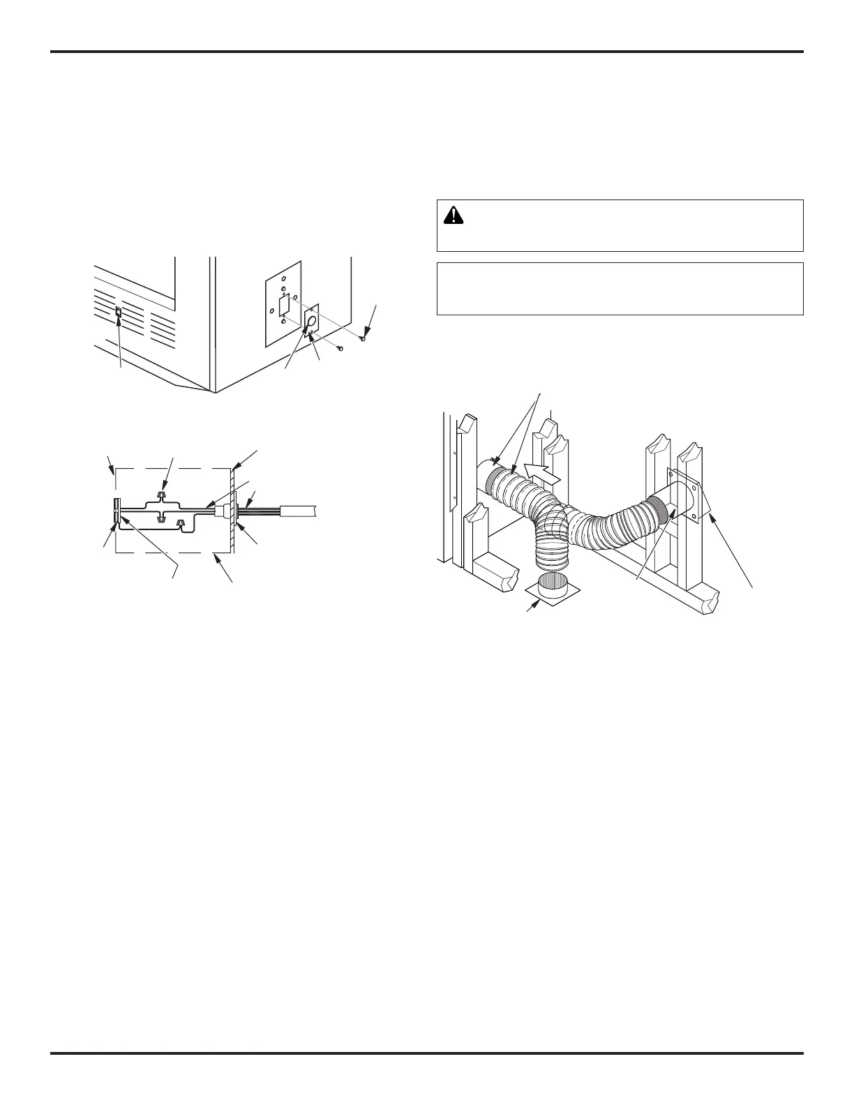
FAN/BLOWER KIT ASSEMBLY
Fanorblowerkitisoptionalwiththisreplace(forcirculatingmodels
only).UseofblowersorfansotherthanthosemanufacturedbyIHP
voidswarranty.Fanisoperatedbypressingrockerswitch(seeFigure
6)inlowerrighthandcornerofreplaceface.Blowerisoperatedby
turningcontrolknob(notshown).
Fan/blower kit electrical connections are made through electrical
cover plate on side of fireplace a shown in Figure 6.
FIREPLACE INSTALLATION Continued
Wiring Instructions
1. Remove electrical cover plate with bushing from fireplace by
removing 2 sheet metal screws as shown in Figure 6.
2. Slide power source wiring through electrical bushing opening
and electrical cover plate and make all necessary connections.
3. Slide all wiring connections in electrical housing as shown in
Figure 6.
4. Secure electrical cover plate with screws previously removed.
Note:Electricalhousing and coverplatehavesharpedges.Wear
protective gloves.
Electrical
Bushing
Electrical
Cover
Plate
Rocker
Switch
Figure 6 - Fan Switch-Electrical Bushing
Electrical
Housing
Wire Nut (3x)
(Not Supplied)
Outer Wrapper
of Fireplace
Electrical Cover
Plate and
Electrical Bushing
Fireplace Chassis
Ground
To Power
Source
Receptacle
(Supplied)
Power Source Wiring
(Not Supplied)
Prewired Receptacle
and Ground
Sheet
Metal
Screws
Figure 7 - Outside Air Kit
Secure to Collars with Metal Tape, Screws
or Straps (Min. of 1/4" x 20" in size)
Air Inlet
Location
Must Allow
For Bushes
or Snow
Vent Hood
Required for
Wall Installation
Air Inlet
Eyebrow
Vented Crawl Space
(Check Local Codes
Before Installing in a
Vented Crawl Space)
VENTING INSTALLATION
OPTIONAL OUTSIDE AIR KIT (MODEL AK4/AK4F)
Installationofoutsideairkitshouldbeperformedduringroughfram-
ingofreplaceduetothenatureofit'slocation.Outsidecombustion
airisaccessedthroughaventedcrawlspace(AK4F)orthrougha
sidewall(AK4).SeeFigure7forinstructionofoperatingairkit.
CAUTION: Combustion air inlet ducts shall not
terminate in attic space.
The maximum height for the air vent can not exceed
3 feet below the flue gas outlet of the termination.
CHIMNEY PIPE
AnIHPchimneysystemconsistsof12",18",24",36"and48"snap-
lock, double-wall pipe segments, planned for maximum adaptability
toindividualsiterequirements.Actuallengths gained after tting
overlapsmustbetakenintoconsideration(linealgain)andaregiven
inlinealgainchart(seeFigure8,page8).
Linealgainisactualmeasurablelengthofapartaftertwoormore
parts are connected.