32
A2SDi-H-TP4F/TF User's Manual
Power Button
OH/Fan Fail
NIC1 Active LED
Reset Button
HDD LED
PWR LED
Reset
PWR
3.3V
3.3V Stby
3.3V Stby
Ground
15
3.3V Stby
UID LED
16
1 2
Ground
NIC2 Active LED
Power Fail LED
3.3V
BIOS LICENSE
JTGLED1
JPW1
A2SDi-H-TF
REV:1.02
DESIGNED IN USA
BAR CODE
COM1
JPI2C1
JSD1
BT1
SRW1
SRW2
PRESS FIT
JPTG1
JWD1
JPG1
JBR1
JPME2
JI2C1
JI2C2
PRESS FIT
JSAS1
PRESS FIT
JSAS2
JMD1
1
LEDT1
C
A
LEDT3
C
A
LEDT2
C
A
LEDT4
C
A
LED1
A
JD1
JSMB1
JBT1
JPH1
JPV1
FANA
FAN3
FAN1
FAN2
JF1
JTPM1
JL1
JRT4
JRT3
I-SATA2
I-SATA1
I-SATA3
I-SATA0
UIDLED1
C
A
LEDM1
8-11
4-7
I-SATA
I-SATA
IPMI LAN
DIMMA1
DIMMA2
DIMMB2
DIMMB1
Intel SoC
FCBGA1310
ALWAYS POPULATE DIMMx1 FIRST
CPU SLOT7 PCI-E 3.0 X4
M.2:PCI-E 3.0 X2 / I-SATA
LAN4
10Gb LAN
JPTG1:
2-3:DISABLE
1-2:ENABLE
1-2:ENABLE
JI2C1:
2-3:DISABLE
JI2C2:
1-2:ENABLE
2-3:DISABLE
1-2:NORMAL
JPME2:
2-3:ME MANUFACTURING MODE
RST
ON
PWR
2
NIC
OH/FFX
2-3:NMI
1-2:RST
JWD1:WATCH DOG
PWR
1 LED
HDDNIC
LED
JPI2C1: PWR I2C
LAN2
USB0/1
USB2/3
USB4(3.0)
UID
VGA
LAN1
LAN3
BMC
AST2400
Intel
X557-AT2
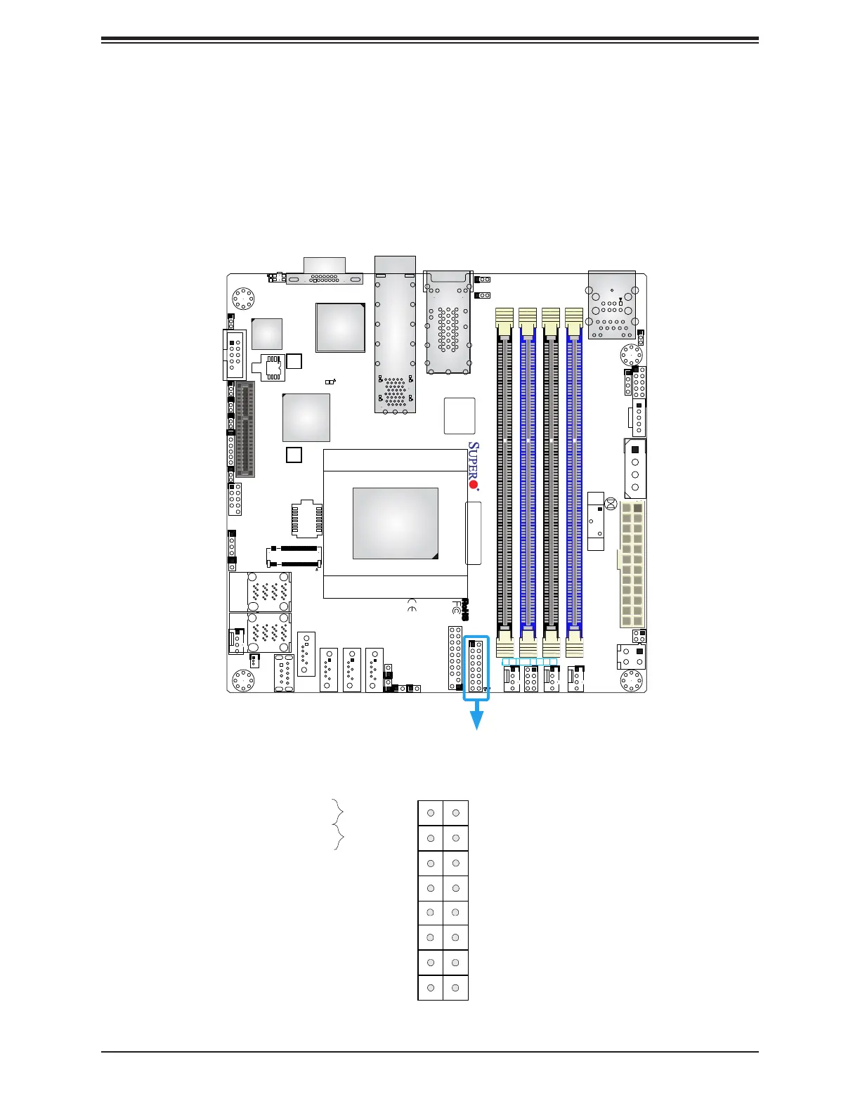
Figure 2-3. JF1 Header Pins
2.6 Front Control Panel
JF1 contains header pins for various buttons and indicators that are normally located on a
control panel at the front of the chassis. These connectors are designed specically for use
with Supermicro chassis. See the gure below for the descriptions of the front control panel
buttons and LED indicators.

 Loading...


