Do you have a question about the Supermicro X10SDV and is the answer not in the manual?
Details the X10SDV Flex ATX Series motherboard features and target audience.
Outlines the structure and content of the manual's chapters and appendices.
Explains symbols for installation/safety and defines warning types.
Provides contact addresses, phone numbers, and websites for Supermicro.
Introduces the motherboard and lists items included in the retail box.
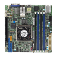
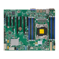
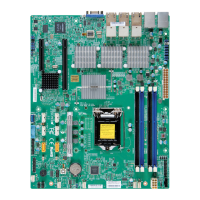
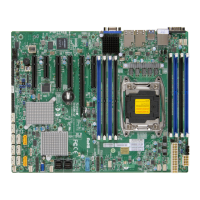
Shows a detailed diagram of the motherboard with labeled components.
Provides a visual guide to component locations on the motherboard.
Compares specifications across different X10SDV motherboard models.
Details jumper functions and lists onboard headers and connectors.
Explains the status and meaning of various motherboard LEDs.
Details CPU, memory, expansion slots, and network controller specifications.
Covers I/O devices, IPMI, BIOS, power, and health monitoring.
Illustrates the functional relationships between major motherboard components.
Details the capabilities and features of the Intel Xeon/Pentium D-1500 processor.
Explains AC power loss recovery, system resource alerts, and health monitoring.
Details ACPI specifications and power supply recommendations.
Provides safety warnings and battery handling instructions.
Instructs on the correct and legal disposal of the product.
Explains precautions to prevent damage from electrostatic discharge.
Lists tools and shows mounting hole locations for installation.
Provides a detailed procedure for physically installing the motherboard into a chassis.
Details supported memory types, speeds, and population/installation guidelines.
Identifies and labels all ports on the rear I/O panel.
Provides pinout details for the COM port and explains VGA port usage.
Describes Gigabit and 10 Gigabit Ethernet ports and their pin definitions.
Details USB 3.0 and USB 2.0 ports, including pin definitions.
Explains the Unit Identifier switch and its associated LEDs for system identification.
Shows the pinout for the front control panel header (JF1).
Details pin definitions for Power LED, Power Button, HDD LED, and NIC LEDs.
Details pin assignments for overheat/fail LEDs and the reset button.
Provides pin definitions for various power connectors and cables.
Details fan header pinouts and chassis intrusion header function.
Explains I2C BMC, DOM PWR, TPM/Port 80, and Overheat LED headers.
Provides pin definitions for speaker and standby power headers.
Explains pinout for Serial Link I/O and System Management Bus headers.
Details NVMe I2C and Power SMBus headers for system monitoring.
Provides pinout for the general purpose I/O header and GPIO register addresses.
Configures VGA enable, CMOS clear, and PCI SMB enable via jumpers.
Details jumpers for watchdog, USB wake-up, ME, BIOS, and BMC settings.
Explains jumpers for enabling/disabling LAN and SAS ports.
Explains the status and meaning of various motherboard LEDs.
Details SATA ports, SAS ports, M.2 socket, and Mini PCI-E slot.
Provides systematic steps for troubleshooting and addresses common problems.
Guides on contacting support and answers frequently asked questions.
Details battery handling, installation, disposal, and RMA process.
Introduces the BIOS setup utility and navigation methods.
Guides on entering BIOS setup and navigating the main screen.
Explains how to set system date/time and view memory status.
Covers boot feature settings, power configuration, and CPU settings.
Details CPU features like spread spectrum, Hyper-Threading, and power states.
Configures DRAM power limits, chipset features, and PCI-E link speeds.
Covers SATA controller, modes, and South Bridge USB configuration.
Outlines settings for Server Management Engine (ME) and PCI/PnP.
Configures system passwords, CSM, secure boot, boot options, and exit.
Lists beep codes and LED indicators for POST errors.
Guides on installing drivers and utilities from CD/DVD or FTP.
Details the installation of SuperDoctor5 for system health monitoring.
Introduces UEFI BIOS and the process for recovering the BIOS image.
Explains the Dual Boot Block feature for BIOS crisis recovery and its usage.
| Form Factor | Mini-ITX |
|---|---|
| Processor Support | Intel Xeon D-1500 Series |
| CPU Socket | FCBGA1667 |
| Memory Type | DDR4 ECC RDIMM/LRDIMM |
| Video Outputs | 1x VGA |
| Memory Slots | 4 |
| Storage Interface | 6x SATA3 |
| Expansion Slots | 1x PCIe 3.0 x16 |
| CPU | Integrated Intel Xeon D-1500 series |
| Chipset | Intel Xeon D-1500 SoC |
| Memory Support | Up to 128GB |
| Power Connector | 24-pin ATX, 8-pin EPS |
