Do you have a question about the Supermicro X10SRH-CF/CLN4F and is the answer not in the manual?
Provides an overview of the X10SRH-CF/CLN4F motherboard and its capabilities.
Details the structure and content of the user manual by chapters and appendices.
Explains the symbols and conventions used throughout the manual for clarity.
Provides contact information for Supermicro headquarters, Europe, and Asia-Pacific offices.
Introduces the motherboard, lists included items, and provides useful links.
Details the Intel C612 Express chipset features and capabilities.
Describes special features like Recovery from AC Power Loss.
Explains PC health monitoring features including temperature and voltage.
Details ACPI features for power management and system events.
Provides guidelines and warnings for ATX power supply installation.
Describes the Super I/O functions, including serial ports and ACPI support.
Presents industry-standard warnings regarding safety and handling, including battery.
Provides precautions for handling static-sensitive components to prevent ESD damage.
Guides through the process of installing the motherboard into a chassis.
Details the procedures for installing the CPU and its heatsink.
Provides instructions for installing and removing DDR4 memory modules.
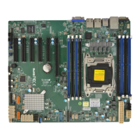
Identifies and describes the various connectors and I/O ports on the motherboard.
Explains the pin-out definitions for onboard headers and connectors.
Details the function and configuration of various motherboard jumpers.
Describes the function and status of onboard LEDs for LAN and system indicators.
Details the SATA and SAS connectors, including their pin definitions.
Outlines procedures for troubleshooting common system issues like no power or no video.
Guides users on how to contact technical support and what information to provide.
Answers common questions regarding BIOS updates, memory support, and hardware.
Provides instructions for removing, installing, and disposing of the CMOS battery.
Explains the process for obtaining warranty service and returning products.
Introduces the UEFI BIOS setup utility and its navigation.
Describes the main BIOS setup screen and its displayed information.
Details various advanced BIOS settings for system configuration.
Explains how to configure SMBIOS event log settings and view logs.
Covers IPMI settings, System Event Log, and BMC network configuration.
Allows configuration of system security settings, including passwords.
Details boot configuration options, boot mode, and boot order priorities.
Explains options for saving BIOS settings, discarding changes, and exiting.
Lists BIOS error beep codes, their messages, and descriptions.
Guides on downloading and installing system drivers and utilities.
Details the installation and usage of the SuperDoctor5 hardware monitoring program.
Provides a general overview of the Unified Extensible Firmware Interface (UEFI).
Explains the structure of UEFI BIOS flash chip and recovery process.
Details the process of recovering BIOS using a USB-attached device.
Introduces the Dual Boot Block feature for BIOS recovery on X10 Grantley platforms.
Guides on performing Dual Boot Block recovery using the IPMI GUI browser.
Details how to perform Dual Boot Block recovery using IPMI Command Sets.
| Form Factor | ATX |
|---|---|
| CPU Socket | LGA 2011-3 |
| Chipset | Intel C612 |
| Memory Slots | 8 |
| Video Ports | 1 x VGA |
| Supported Memory Types | DDR4 |
| SAS | 8 x SAS3 (12Gbps) ports via LSI 3008 controller |
| M.2 | 1 x M.2 |
| SATA | 6 x SATA 6Gb/s |
