Chapter 2: Installation
2-13
DESIGNED IN USA
1.00REV:
X10SRH-CF
SAS CODE
1
BIOS
LICENSE
IPMI CODE
MAC CODE
BAR CODE
321
123
PCH SLOT2 PCI-E 2.0 X4(IN X8)
LGA2011-3
1
1
PCH
C610
i350
LSI
3008
BMC
BIOS
SP1
I-SATA5
S-SATA2
S-SATA1
S-SATA0
I-SATA3
I-SATA2
I-SATA1
I-SATA0
I-SATA4
S-SATA3
JSTBY1
JPI2C1
FANA
FAN3
FAN2
FAN1
FAN4
FANB
FANC
FAN5
BT1
JBT1
LEDM1
LE2
JPWR1
JP4
JIPMB1
JSD2
JSD1
JVR1
JPL1
JVRM1
JVRM2
JBR1
JI2C1
JI2C2
JPB1
JPG1
JWD1
JPME2
JPS1
T-SGPIO3
T-SGPIO2
T-SGPIO1
J23
JD1
JF1
JTPM1
LEDS1
JF2
J33
JOH1
JL1
JPSAS1
J24
SATA DOM
+
POWER
+
POWERSATA DOM
UID-LED
X
LED
2-3:DISABLE
1-2:ENABLE
JPS1:SAS
1-2:ENABLE
2-3:DISABLE
LAN2/LAN4
L-SAS4-7
L-SAS0-3
1-2:ENABLE
2-3:DISABLE
JPB1:BMC
CPU
CPU SLOT6 PCI-E 3.0 X8(IN X16)
CPU SLOT5 PCI-E 3.0 X8
CPU SLOT4 PCI-E 3.0 X8
PCH SLOT3 PCI-E 2.0 X2(IN X4)
JPME2
2-3:ME MANUFACTURING MODE
1-2:Normal
USB0/1
DIMMC2
PWR LED1-3:
JD1:
SPEAKER4-7:
JBR1
1-2:Normal
2-3:BIOS recovery
:TPM/PRO80
CHASSIS
INTRUSION
USB8/9
JF1
USB6/7
LED
NMI
PWR
X
USB2/3(3.0)
HDD
NIC
1
JWD1:Watch Dog
1-2:RST
2-3:NMI
DIMMA2
DIMMA1
USB10(3.0)
FF
2
NIC
OH
LAN1/LAN3
RST
PWR
USB4/5
ON
1-2:ENABLE
2-3:DISABLE
JPG1:VGA
JI2C1/JI2C2
I2C bus for PCI-E slot
CPU SLOT7 PCI-E 3.0 X4(IN X8)
COM2
COM1
DIMMB1
DIMMD2
DIMMD1
DIMMC1
IPMI_LAN
UID-SW
USB11(3.0)
SATA DOM
POWER
CLEARCMOS
JPL1:LAN1/2/3/4
1-2:ENABLE
VGA
2-3:DISABLE
DIMMB2
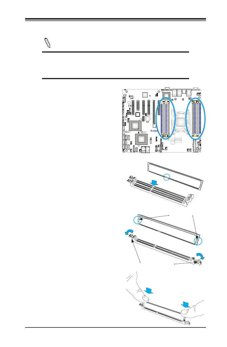
2-5 Installing DDR4 Memory
Note: Check the Supermicro website for recommended memory mod-
ules.
CAUTION
Exercise extreme care when installing or removing DIMM
modules to prevent any possible damage.
DIMM Installation
1. Insert the desired number of DIMMs
into the memory slots, starting with
DIMMA1 (Channel A, Slot 1, see
the next page for the location). For
the system to work properly, please
use the memory modules of the
same type and speed in the same
motherboard.
Release Tabs
Notches
2. Push the release tabs outwards on
both ends of the DIMM slot to unlock
it.
Press both notches
straight down into
the memory slot.
3. Align the key of the DIMM mod-
ule with the receptive point on the
memory slot.
4. Align the notches on both ends of
the module against the receptive
points on the ends of the slot.
5. Use two thumbs together to press
the notches on both ends of the
module straight down into the slot
until the module snaps into place.
6. Press the release tabs to the lock
positions to secure the DIMM module
into the slot.

 Loading...


