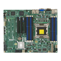
Do you have a question about the Supermicro A2SDi-4C-HLN4F and is the answer not in the manual?
Manual content and intended audience for system integrators, IT technicians, and end users.
Details the Supermicro A2SDi-HLN4F Series motherboard features and specifications.
Explains symbols and conventions used throughout the manual for clarity and safety.
Supermicro's main contact address, phone, fax, and email information.
Contact information for Supermicro's Europe and Asia-Pacific regions.
Guidelines for handling static-sensitive components to prevent damage.
Steps and tools required for installing the motherboard into a chassis.
Lists common beep codes for POST errors and their descriptions.
Guidance on installing necessary software, drivers, and utilities for the motherboard.
Instructions for recovering the UEFI BIOS image in case of corruption.
Lists the items included in the retail box for the Supermicro motherboard.
Provides links to download drivers, manuals, and product safety information.
Detailed table of jumpers, LEDs, and connectors with their descriptions and default settings.
Details the Intel Atom SoC processor and memory support specifications.
Lists expansion slots, network, graphics, and I/O device details.
Covers BIOS features, power management, and system health monitoring.
Details fan control, TPM, UID, and system alerts.
Details the Intel Atom SoC, its architecture, and supported technologies.
Highlights health monitoring and AC power loss recovery.
Monitors voltage, fan status, and temperatures for system health.
Describes ACPI for flexible hardware interface and power management.
Precautions and measures to protect against electrostatic discharge (ESD).
Guidance on safely unpacking the motherboard to avoid static damage.
Tools needed and guides on aligning mounting holes for motherboard installation.
Guides on identifying and aligning motherboard mounting holes with chassis.
Specifies supported memory configurations for different motherboard models.
Provides optimal memory population order for balanced performance.
Step-by-step guide for inserting memory modules into DIMM slots.
Instructions for safely removing memory modules from DIMM slots.
Identifies and describes the I/O ports located on the rear of the motherboard.
Describes rear panel USB ports and internal USB headers with pin definitions.
Details the COM header (COM1) and its pin definitions for serial communication.
Explains the JF1 header pins for chassis front panel buttons and LEDs.
Details the Power LED (LED1) and HDD LED connections on JF1.
Explains connections for Reset and Power buttons on JF1.
Details connections for Overheat/Fan Fail and NIC activity LEDs on JF1.
Details power connectors: ATX, HDD Power, and DC Power.
Explains the pin definitions for ATX, 4-pin HDD, and 4-pin DC power connectors.
Describes Fan Headers (FAN1-FAN3, FANA) and Speaker header (JD1).
Details the 10-pin JGP1 header for general purpose I/O functions.
Explains the JTPM1 header for connecting a Trusted Platform Module (TPM).
Details DOM power connector and chassis intrusion header.
Details the JPI2C1 and JSMB1 headers for system management.
Details LAN activity LEDs and thermal sensor headers.
Details SATA3.0 ports and the M.2 slot availability for different models.
Explains the UID switch and LED for system identification.
Describes the function of jumpers and how to set them.
Instructions for clearing CMOS settings using the JBT1 jumper.
Configures VGA port and ME Manufacturing Mode using jumpers.
Details the Watch Dog function controlled by JWD1 jumper for system reboots.
Instructions for recovering BIOS settings using the JBR1 jumper.
Configures SMBus connection to PCI-E slots using JI2C1 and JI2C2 jumpers.
Enables or disables the four LAN ports using the JPL1 jumper.
Describes LAN port activity LEDs and IPMI LAN LED status.
Describes the Power LED (LED1) and BMC Heartbeat LED (LEDM1) status.
General procedures for troubleshooting system issues.
Troubleshooting steps for systems that do not power on.
Troubleshooting steps for systems failing to boot or display POST.
Procedures for identifying and resolving memory-related errors.
Causes and solutions for loss of CMOS setup information.
Troubleshooting steps for system instability during/after OS installation.
Steps to take before contacting technical support.
Answers common questions about memory support and BIOS updates.
Instructions for removing, installing, and disposing of the CMOS battery.
Guidance on environmentally responsible disposal of used batteries.
Procedures for obtaining warranty service and RMA numbers.
Overview of the AMIBIOS Setup utility and its features.
How to enter the BIOS Setup Utility using the <Delete> key.
How to change the system date and time in the BIOS.
Displays the BIOS ROM version and build date.
Shows total memory and indicates the default speed of installed memory.
Configures boot display options like Quiet Boot and Wait for F1.
Sets the power-on state for the Numlock key.
Configures Watch Dog, Power Button, and AC Power Loss behavior.
Displays CPU model, ID, microcode, frequency, and cache info.
Manages CPU power saving and frequency settings.
Configures CPU Turbo boost and thermal monitoring modes.
Manages CPU power states for enhanced efficiency.
Configures CPU prefetchers, ACPI T-States, and security features.
Enables Intel Virtualization Technology and Extended APIC.
Configures encryption, power limits, and active processor cores.
Configuration for chipset and North Bridge memory information.
Enables Intel VT-d and Interrupt Remapping support.
Selects how data is saved after power loss (NVDIMM).
Configures notifications for power button, ME, and PMC events.
Enables NVDIMM interleaving support for memory speed.
Manages NVDIMM restore, erase, and battery settings.
Configures memory frequency, parity, and CAS latency.
Enables CPU correction of memory errors and thermal throttling.
Configures legacy USB support, XHCI hand-off, and port emulation.
Selects SATA ports and PCIe lanes on expansion slot.
Configures SATA controller 0, Link Power Management, and SGPIO/LED.
Displays information for SATA drive entries.
Configures SATA controller 1, Link Power Management, and SGPIO/LED.
Displays information for SATA drive entries.
Displays ME information: configuration, firmware versions, features, status.
Displays PCI information: driver version and common settings.
Configures 4G Decoding and SR-IOV support.
Configures PCI-E payload, read request, and power management.
Selects types for Onboard LAN and Video Option ROMs.
Configures network stack, PXE support, and wait times.
Configuration for Serial Port 1.
Specifies base I/O and IRQ addresses for Serial Port 1.
Configures COM1 Console Redirection, including terminal type and speed.
Configures COM1 parity, stop bits, flow control, and keys.
Enables the SOL port for Console Redirection.
Configures SOL parity, stop bits, flow control, and key support.
Configures EMS Console Redirection, including port and terminal type.
Configures ACPI power management settings.
Supports Windows Hardware Error Architecture for error handling.
Manages TPM security support and state.
Manages TPM state, pending operations, and device selection.
Configures PCR banks and security hierarchies for TPM.
Configures TPM version and hierarchy settings.
Configuration for iSCSI initiator.
Changes link speed and duplex for the current network port.
Configures Wake On LAN and LED blink duration.
Displays NIC driver version, PBA, device name, and MAC addresses.
Configures SMBIOS Event Log settings.
Enables/disables PCIe, Memory, and System Boot event logging.
Configures event log erasing and actions when the log is full.
Sets standard SMBIOS event log parameters like boot event logging.
Allows viewing events in the SMBIOS event log.
Configures Intelligent Platform Management Interface (IPMI) settings.
Indicates the IPMI firmware revision and status.
Manages SEL components and clearing settings.
Configures SEL full log handling and IPMI LAN settings.
Displays Station MAC and Gateway IP addresses.
Configures IPMI VLAN and function support.
Configures system security settings.
Configures password checks and administrator/user passwords.
Configures Secure Boot features.
Enables secure boot and selects modes (Standard/Custom).
Manages CSM support, key databases, and factory defaults.
Manages Key Exchange Key, signatures, and timestamps.
Uploads and installs an OSRecovery Signature.
Configures Boot Settings.
Prioritizes the order of bootable devices.
Sets the system boot order for UEFI boot options.
Sets boot order for detected devices and drives.
Manages boot options by adding or deleting them.
Options for saving changes and resetting or exiting.
Saves or discards changes and exits the BIOS setup.
Restores factory or user-defined default BIOS settings.
Overrides boot option priorities for immediate boot.
Lists common beep codes for POST errors and their descriptions.
Guidance on obtaining and installing drivers and utilities from FTP or website.
Details SuperDoctor 5, a hardware monitoring program.
Standard warnings regarding battery replacement and disposal.
Instructions on proper disposal of the product according to national laws.
Explains UEFI interface and its role in system boot.
Details on recovering the UEFI BIOS image using recovery block.
Procedure to recover main BIOS image using a USB device.
File systems supported by recovery block (FAT) for USB devices.
Description of the BIOS Recovery menu and proceeding with flash update.
Steps to extract BIOS package, enter BIOS setup, and load defaults.
| Form Factor | Mini-ITX |
|---|---|
| CPU Core Count | 4 |
| Memory Type | DDR4 |
| Storage | 4 x SATA3 |
| Power Connector | 24-pin ATX |
| Operating Temperature | 0°C to 60°C |
| CPU | Intel Atom C3558 |
| Chipset | Intel SoC |
| Max Memory | 64 GB |
| Network | 4x Gigabit Ethernet |
| USB Ports | 2x USB 3.0, 2x USB 2.0 |
| Video Outputs | 1x VGA |
| Dimensions | 6.7 in x 6.7 in (170 mm x 170 mm) |
| Memory Slots | 2 |
