41
Chapter 2: Installation
BIOS LICENSE
JTGLED1
JPW1
A2SDi-2C-HLN4F
REV:1.00
DESIGNED IN USA
BAR CODE
COM1
JPCIE1
JSD1
1
SRW1
SRW2
JUIDB
JPL1
JWD1
JPG1
JBR1
JPME2
PRESS FIT
JSAS1
PRESS FIT
JSAS2
JMD1
JB3
LED1
JD1
JSMB1
JGP1
1
JBT1
JPH1
JPV1
FANA
FAN1
FAN2
JF1
JTPM1
JL1
JRT4
JRT3
I-SATA2
I-SATA1 I-SATA3
I-SATA0
JUSB3A1
UIDLED1
A
LEDM1
FANA
FAN3
SUPERDOM
SATA DOM+POWER
8-11
4-7
I-SATA
I-SATA
IPMI LAN
DIMMA1
DIMMA2
DIMMB2
DIMMB1
CPU
ALWAYS POPULATE DIMMA1 FIRST
CPU SLOT7 PCI-E 3.0 X4
M.2:PCI-E 3.0 X2 / I-SATA
LAN4
INTRUSION
JD1:
1-4:SPEAKER
CHASSIS
JL1:
JPB1:BMC
1-2:ENABLE
2-3:DISABLE
1-2:ENABLE
JI2C1:
2-3:DISABLE
JI2C2:
1-2:ENABLE
2-3:DISABLE
1-2:NORMAL
JPME2:
2-3:ME MANUFACTURING MODE
RST
JF1
ON
PWR
2
NIC
OH/FFX
2-3:NMI
1-2:RST
JWD1:WATCH DOG
PWR
1 LED
HDDNIC
LED
JPI2C1
JBR1
1-2:NORMAL
2-3:BIOS RECOVERY
LAN2
USB0/1
USB2/3
USB4(3.0)
VGA
LAN1
LAN3
BT1
1
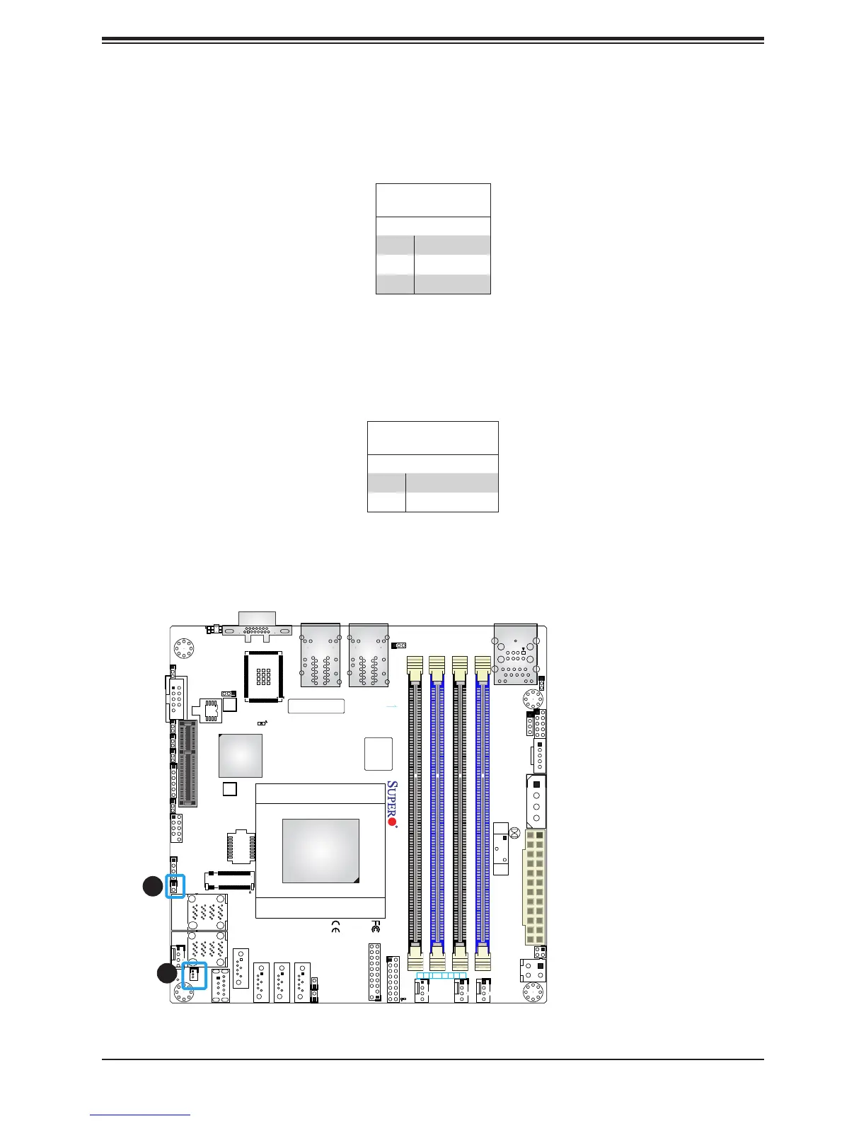
2
1. SATA DOM
2. Chassis Intrusion
Disk-On-Module Power Connector
The Disk-On-Module (DOM) power connector at JSD1 provides 5V power to a solid-state DOM
storage device connected to one of the SATA ports. Refer the table below for pin denitions.
DOM Power
Pin Denitions
Pin# Denition
1 5V
2 Ground
3 Ground
Chassis Intrusion
A Chassis Intrusion header is located at JL1 on the motherboard. Attach the appropriate cable
from the chassis to the header to inform you when the chassis is opened.
Chassis Intrusion
Pin Denitions
Pin# Denition
1 Intrusion Input
2 Ground

 Loading...


