44
A2SDi-H-TP4F/TF User's Manual
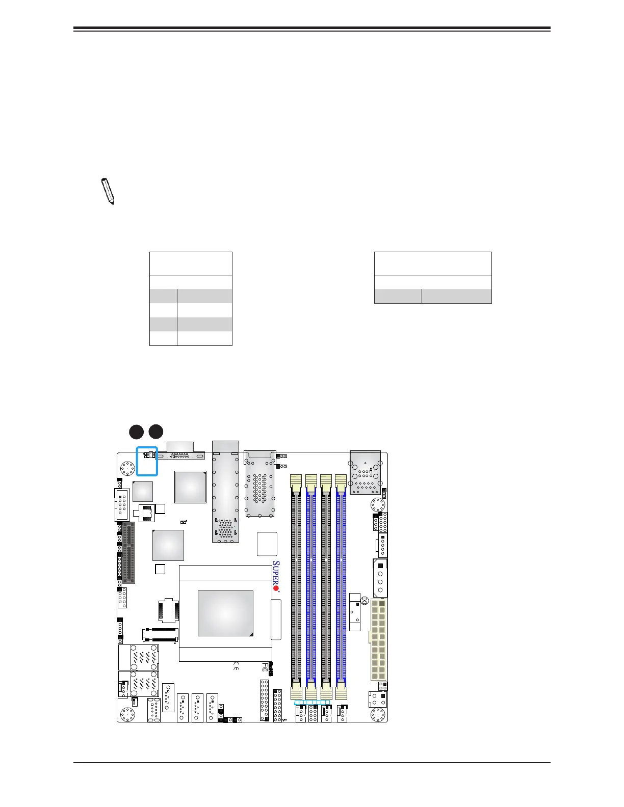
Unit Identier Switch/UID LED Indicator
A Unit Identier (UID) switch and an LED Indicator are located on the motherboard. The UID
switch is located at UID, which is next to the VGA port on the back panel. The UID LED
(UIDLED1) is located next to the UID switch. When you press the UID switch, the UID LED
will be turned on. Press the UID switch again to turn off the LED indicator. The UID Indicator
provides easy identication of a system unit that may be in need of service.
Note: UID can also be triggered via IPMI on the motherboard. For more information
on IPMI, please refer to the IPMI User's Guide posted on our website at http://www.
supermicro.com.
UID Switch
Pin Denitions
Pin# Denition
1 Ground
2 Ground
3 Button In
4 Button In
UID LED
Pin Denitions
Color Status
Blue: On Unit Identied
BIOS LICENSE
JTGLED1
JPW1
A2SDi-H-TF
REV:1.02
DESIGNED IN USA
BAR CODE
COM1
JPI2C1
JSD1
BT1
SRW1
SRW2
PRESS FIT
JPTG1
JWD1
JPG1
JBR1
JPME2
JI2C1
JI2C2
PRESS FIT
JSAS1
PRESS FIT
JSAS2
JMD1
1
LEDT1
C
A
LEDT3
C
A
LEDT2
C
A
LEDT4
C
A
LED1
A
JD1
JSMB1
JBT1
JPH1
JPV1
FANA
FAN3
FAN1
FAN2
JF1
JTPM1
JL1
JRT4
JRT3
I-SATA2
I-SATA1
I-SATA3
I-SATA0
UIDLED1
C
A
LEDM1
8-11
4-7
I-SATA
I-SATA
IPMI LAN
DIMMA1
DIMMA2
DIMMB2
DIMMB1
Intel SoC
FCBGA1310
ALWAYS POPULATE DIMMx1 FIRST
CPU SLOT7 PCI-E 3.0 X4
M.2:PCI-E 3.0 X2 / I-SATA
LAN4
10Gb LAN
JPTG1:
2-3:DISABLE
1-2:ENABLE
1-2:ENABLE
JI2C1:
2-3:DISABLE
JI2C2:
1-2:ENABLE
2-3:DISABLE
1-2:NORMAL
JPME2:
2-3:ME MANUFACTURING MODE
RST
ON
PWR
2
NIC
OH/FFX
2-3:NMI
1-2:RST
JWD1:WATCH DOG
PWR
1 LED
HDDNIC
LED
JPI2C1: PWR I2C
LAN2
USB0/1
USB2/3
USB4(3.0)
UID
VGA
LAN1
LAN3
BMC
AST2400
Intel
X557-AT2
1
1. UID Switch
2. UID LED
2

 Loading...


