33
Chapter 2: Installation
2
JLANLED3
JLANLED2
4
JLANLED1
JSFPLED1
2
1
JFPCLED1
C
A
LEDT2
LEDT4
A
C
COM1
1
5
PRESS FIT
CG13
CG11
CG7
CG6
CG1
CG2
CG3
CG4
CG5
L20
L19
L1
SFP1
BAR CODE
BIOS LICENSE
DESIGNED IN USA
A2SDV-4C-LN8F
REV:1.01
11
10
6
1
M*
20
19
2
1
JF1
67
57
JMD2
JMD1
1
7475
12
13
1
JPW1
JPI2C1
JSD1
BT1
SRW2
SRW1
SRW3
SRW4
JUIDB
JPL1
JI2C2
JI2C1
JWD1
JPG1
JPME2
JSEL1
JPL4
JPL3
JPL2
JBR1
DIMMA2
DIMMB2
DIMMA1
DIMMB1
C
A
LEDT1 LEDT3
A
C
JSMB1
JD1
2
1
JGP1
JBT1
JPH1
4
3
2
JPV1
FAN2
FAN1
FANB
FAN3
FANA
1
2
20
JL1
JRT3
1
1
I-SATA1
I-SATA2
I-SATA3
I-SATA4
I-SATA0
1
4
LEDM1
A
C
UIDLED1
A
ALWAYS POPULATE DIMMx1 FIRST
LN10PF: LAN1-2
LN10PF: LAN3-10 LN8F: LAN1-8
USB 4 (3.1 Gen 1)
eUSB
USB 2/3
USB 0/1
(3.1 Gen 1)
IPMI LAN
CPU
VGA
CPU SLOT7 PCI-E 3.0 X4
NMIX
CPU SLOT6 PCI-E 3.0 X4
PWR
LED
HDD
LED
NIC
2
NIC
1
OH/FF
RST X
JF1
ON
PWR
JIPMB1
JTPM1
CM CODE
LED1
JRT4
BMC
AST2400
1
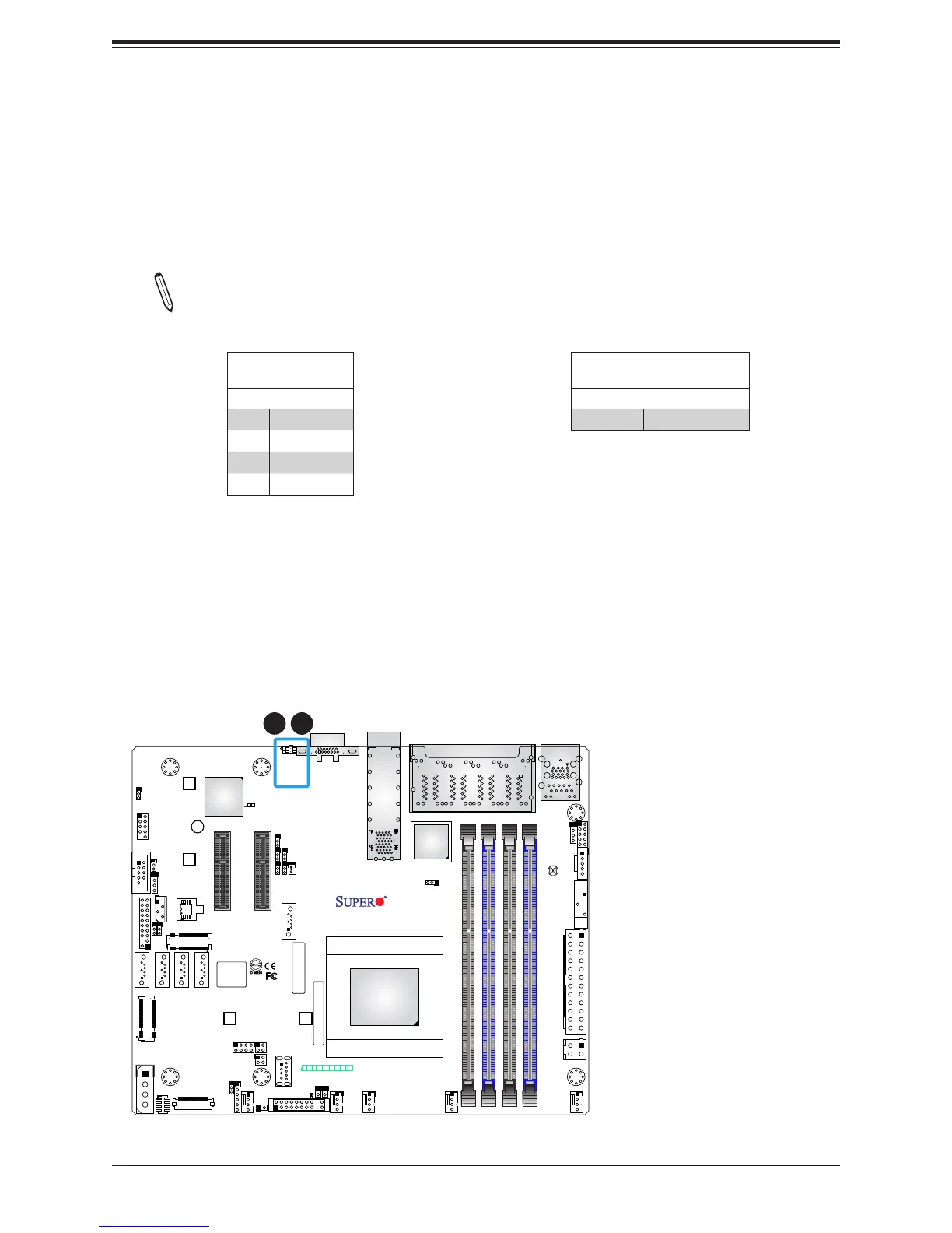
1. UID Button
2. UID LED
2
UID Button
Pin Denitions
Pin# Denition
1 Ground
2 Ground
3 Button In
4 Button In
UID LED
Pin Denitions
Color Status
Blue: On Unit Identied
Unit Identier Button/UID LED Indicator
A Unit Identier button and an LED indicator are located on the motherboard. The UID
button (JUIDB) is located next to the VGA port on the back panel. The UID LED is located at
UIDLED1, next to the UID button. When you press the UID button, the UID LED will be turned
on. Press the UID button again to turn off the LED indicator. The LED indicator provides easy
identication of a system unit that may be in need of service.
Note: UID can also be triggered via IPMI on the motherboard. For more information
on IPMI, please refer to the IPMI User's Guide posted on our website at https://www.
supermicro.com/support/manuals/.