13
Chapter 1: Introduction
Connector Description
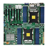
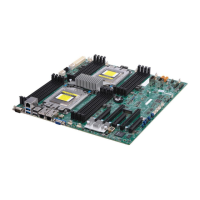
P1-DIMMA1~P1-DIMMH1 DIMM sockets for CPU1
P2-DIMMA1~P2-DIMMH1 DIMM sockets for CPU2
CPU2 SLOT 1 X8 PCIE 3.0 Slot via CPU2
CPU1 SLOT 2, SLOT 4 X16 PCIE 3.0 Slot via CPU1
CPU1 SLOT 3, SLOT 5 X8 PCIE 3.0 Slot via CPU1
Note: Jumpers, connectors, switches, and LED indicators that are not described in the
preceding tables are for manufacturing testing purposes only, and are not covered in this
manual.
 Loading...
