39
Chapter 2: Installation
Power LED
The Power LED connection is located on pins 15 and 16 of JF1.
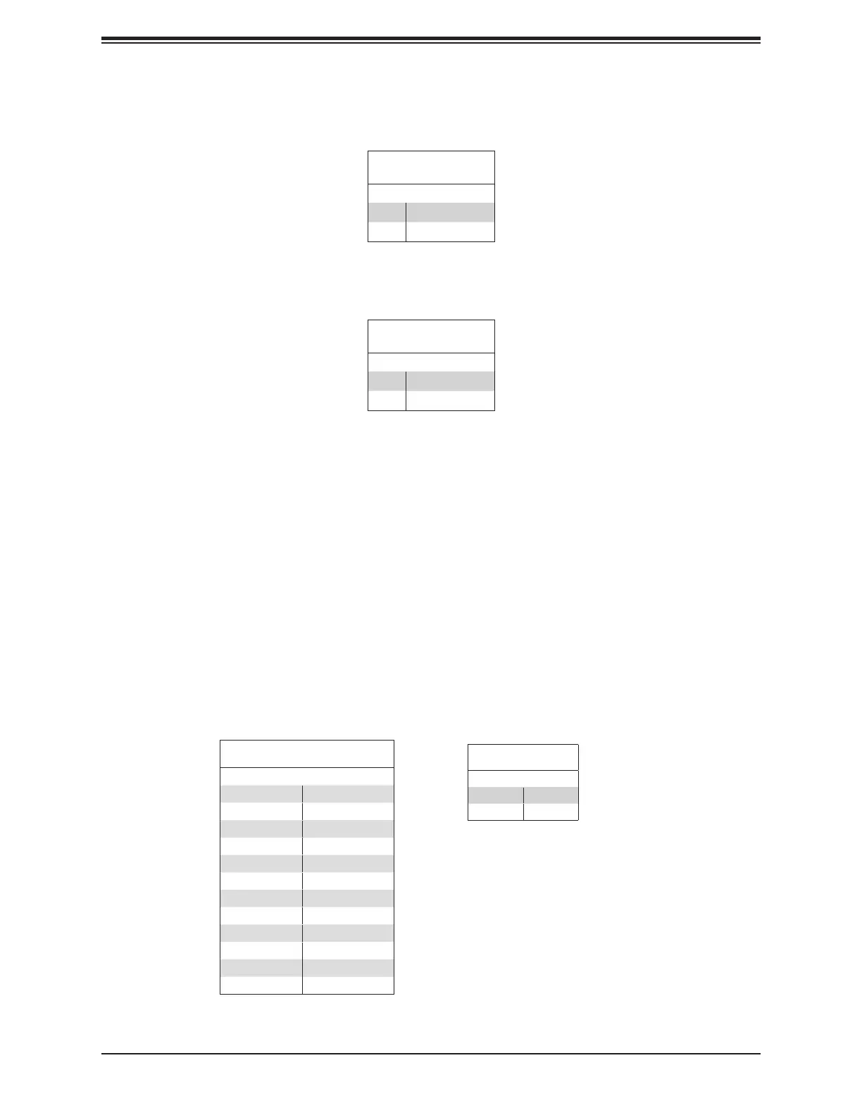
Power LED
Pin Denitions (JF1)
Pin# Denition
15 3.3V
16 Power LED
NMI Button
The non-maskable interrupt button header is located on pins 19 and 20 of JF1.
NMI Button
Pin Denitions (JF1)
Pin# Denition
19 Control
20 Ground
2.7 Connectors
Power Connections
Main Power Supply Connector
The primary power supply connector (JPWR1) is an ATX power connector that the power
supply plugs into directly.
12V 8-pin Auxilliary Power Connectors
JPWR2 and JPWR3 are 8-pin ATX power inputs to provide auxilliary power to the processors
that are installed in the system. Refer to the table below for pin denitions.
ATX Power 24-pin Connector
Pin Denitions (JPW1)
Pin# Denition Pin # Denition
13 +3.3V 1 +3.3V
14 -12V 2 +3.3V
15 Ground 3 Ground
16 PS_ON 4 +5V
17 Ground 5 Ground
18 Ground 6 +5V
19 Ground 7 Ground
20 Res (NC) 8 PWR_OK
21 +5V 9 5VSB
22 +5V 10 +12V
23 +5V 11 +12V
24 Ground 12 +3.3V
12V 8-pin Power Connec-
tor Pin Denitions
Pins Denition
1 through 4 Ground
5 through 8 +12V

 Loading...


