Do you have a question about the Supermicro SSE-X24S and is the answer not in the manual?
Provides information for configuring basic functionalities through the Web graphical user interface (GUI).
Describes the SSE-G24-TG4 and SSE-G48-TG4 1/10-Gigabit Ethernet switches, including uplink ports and LAN interfaces.
Lists the components included with SSE-G24-TG4/SSE-G48-TG4 and SSE-X24S/R switches.
Details the features of the Layer 2/3 1/10 and 10-Gigabit Ethernet switches.
Outlines the physical characteristics such as form factor, dimensions, and weight of the switches.
Provides contact information for Supermicro headquarters, Europe, and Asia-Pacific regions.
Explains industry standard warnings provided to warn users of potential bodily injury.
Provides instructions to read before connecting the system to the power source.
Details short-circuit protection requirements for building installations (250V, 20A).
Instructs to disconnect all power sources before accessing chassis interior.
States that only trained and qualified personnel should install or service the equipment.
Specifies that the unit is for restricted access areas, requiring special tools for entry.
Warns about explosion danger if battery is replaced incorrectly and provides disposal instructions.
Advises removing all connections to de-energize the unit with multiple power supply connections.
Warns about hazardous voltage/energy on the backplane during operation and advises caution.
Stresses that equipment installation must comply with local and national electrical codes.
Informs that product disposal must follow all national laws and regulations.
Warns that fans may still be turning when removing the fan assembly.
Advises using only provided/designated cables and adaptors to prevent malfunction or fire.
Provides procedures for installing Layer 2/3 Gigabit Ethernet switches.
Explains configuration methods via web-based utility or command line.
Details the procedures for upgrading firmware using TFTP or the network.
Guides on booting the switch using a fallback firmware image.
Provides steps to recover switch functionality with a working firmware image.
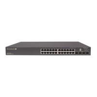
Details the ports and LED indicators for the SSE-G24-TG4 switch.
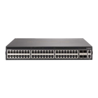
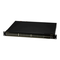
Details the ports and LED indicators for the SSE-G48-TG4 switch.
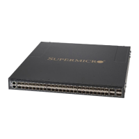
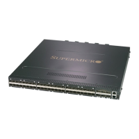
Details the ports and LED indicators for the SSE-X24S/R switch.
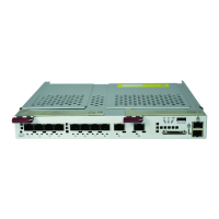
Details the ports and LED indicators for the SSE-X3348S/R switch.
Details the ports and LED indicators for the SSE-X3348T/R switch.
Describes common front-mounted ports like RJ45, Combo, and 10-Gb/s module bays.
Lists and describes the LED indicators for the SSE-G24-TG4 and SSE-G48-TG4 switches.
Introduces the web-based interface for managing Layer 2 and Layer 3 switching features.
Explains how to log in to the Supermicro Switch web-based management utility.
Describes the HOME page structure, containing links and menus for control and navigation.
Details the System Management page, offering access to System Settings, IP, File Management, etc.
Explains how to access and configure system-related information and parameters.
Shows system version information including Switch ID, Hardware Version, and Firmware Version.
Guides on managing the switch's IP address, including manual or dynamic configuration.
Covers managing configuration files, including saving and copying.
Explains how to upgrade the switch firmware in Normal or Fallback Memory.
Provides configuration for user accounts, RADIUS, TACACS+, SSH, and SSL.
Allows creation and deletion of local user accounts with privilege levels.
Covers RADIUS server configuration parameters for authentication.
Allows configuration of TACACS retries and selection of an active TACACS server.
Enables configuration of TACACS servers, specifying IP address, port, and connection type.
Configures allowed management nodes for switch access control.
Allows configuration of SSH version and keys for secure shell access.
Configures SSL parameters and generates SSL certificates for HTTPS access.
Enables configuration of logging parameters for syslog buffer and file.
Allows configuration of Access Control Lists, including MAC ACL, IP Standard ACL, and IP Extended ACL.
Configures basic Web GUI settings like session timeout and statistics refresh timer.
Configures SNMP Agent and AgentX sub-agent settings.
Allows setting RMON features and statistics, including Basic Settings, Events, Alarm, Ethernet Statistics, and History.
Enables configuration of Quality of Service (QoS) through Basic Settings, Classmap, and Policymap.
Configures VLAN Class of Service (COS) Queue Mapping Global Settings.
Configures VLAN COS queue scheduling and bandwidth control.
Allows configuration of NTP Settings and Clock Settings for time synchronization.
Supports stacking of switch units, enabling management of master and slave switches.
Details configuration for CX4 cable length for stacking and uplink connections.
Covers Layer 2 features including basic settings, port manager, VLAN, RSTP, MSTP, Link Aggregation, etc.
Provides links to web pages for managing port settings, monitoring, control, and storm control.
Allows configuration of VLAN information, including basic settings, port settings, and static VLANs.
Enables configuration of Dynamic VLAN information, including port settings and GARP timers.
Supports configuration of RSTP or MSTP protocols for Spanning Tree management.
Describes combining physical connections into a single logical link for increased bandwidth and redundancy.
Allows viewing LLDP statistics, errors, neighbors, traffic, and interface traffic.
Provides configuration for 802.1x authentication, including basic settings, port settings, timers, and local AS.
Covers Layer 3 features including IP, IPv6, DHCP Server, DHCP Relay, RIP, OSPF, BGP, RRD, and VRRP.
Enables IP-related configuration through VLAN Interface, IPv4 AddrConf, IP Route, and LoopBack Settings.
Allows performing IPv6-related configurations, including routes, interfaces, ND cache, and address settings.
Helps manage the DHCP server, including basic settings, pool settings, MAC binding, and port binding.
Manages DHCP relay in the switch through basic settings and interface configuration.
Covers RIP protocol configuration including basic settings, interface, neighbors, security, and summarization.
Allows configuration of OSPF protocol through basic settings, area, interface, virtual interface, neighbor, RRD, and aggregation.
Enables configuration of OSPFv3 protocol, including basic settings, interface, area, and external aggregation.
Allows configuration of BGP protocol, including basics, neighbors, MED, local preference, filters, route aggregation, advanced settings, and community.
Manages Route Redistribution (RRD) with the help of BGP, RIP, and OSPF settings.
Provides links to multicast features like IGMP Snooping, Dynamic Multicast, IGMP, PIM, and DVMRP.
Configures IGMP snooping parameters, including basic settings, timers, interface configuration, router ports, and group information.
Allows configuration of the IGMP protocol through basic settings, interface configuration, group information, and source information.
Enables PIM configuration for basic settings, component, interfaces, candidate RPs, threshold, and static RP.
Allows configuration of the DVMRP protocol, including basic settings and interfaces.
Provides access to all statistical information for switch features like Interface, Radius, SNMP, VLAN, etc.
Allows configuration of interface statistics, including Ethernet and Port Channel statistics.
Displays Ethernet statistics, including port index, alignment errors, FCS errors, and collision counts.
Displays port channel interface statistics, including received and transmitted packets, errors, and octets.
Provides RADIUS server statistics, including request packets, access accept/reject counts, and timeouts.
Displays TACACS+ statistics for authentication and accounting events.
Allows configuration of Syslog buffer and Syslog file for logging messages.
Displays RMON Ethernet statistics information for ports.
Provides SNMP statistics for packets, errors, community names, and requests.
Displays Agentx Subagent statistics related to transmit and receive operations.
Allows viewing VLAN statistics through Current DB, Multicast Table, Capabilities, and MAC Address Table.
Displays VLAN filter database entries, including VLAN ID, MAC Address, and Port information.
Provides RSTP statistics, including information, port statistics, and status.
Allows viewing MSTP statistics, including MSTP Information and CIST/MSTI Port Statistics.
Provides Link Aggregation statistics through Port LACP Stats and Neighbor Stats.
Allows viewing LLDP statistics, errors, neighbors, traffic, and interface traffic.
Displays 802.1x session statistics, including port, session ID, frames, and user authentication.
Allows viewing IP statistics, including ARP Cache and ICMP Statistics.
Enables viewing IPv6 statistics, including IPv6 Interface and ICMPv6 statistics.
Allows viewing RIP statistics, including interface statistics and route information.
Enables viewing OSPF statistics, including route information and link state database.
Allows viewing OSPFv3 statistics, including route information and link state database.
Displays VRRP global and router-specific statistics.
Provides IGMP snooping statistics, including clear stats, V1/V2 stats, and V3 stats.
Allows viewing IGMP route statistics, including interface and multicast group information.
Enables viewing PIM statistics for interface, neighbor, BSR, RP set, and mroute information.
Introduces the optional rail kit for easy rack installation of switches.
Guides on inspecting the switch for shipping damage and choosing a suitable rack location.
Details the contents of the rail kit and choosing a setup location with clearance requirements.
Covers rack, general, and lithium battery precautions for safe installation.
Provides information on installing the switch into a rack unit using the CSE-PT52L rail kit.
Details the procedure for installing the inner rails onto the switch.
Provides instructions for assembling and installing the outer rails onto the rack.
Guides on aligning and sliding the switch into the installed rack rails.
Explains the process of installing the switch into a Telco (post style) rack using L-shaped brackets.
| Form Factor | Rack-mountable |
|---|---|
| Switching Capacity | 480 Gbps |
| VLANs Supported | 4K |
| Product Type | Switch |
| Ports | 24 x 10 Gigabit SFP+ |
| MAC Address Table Size | 32K |
| Management | Web, CLI, SNMP |
| Features | Layer 2/3, QoS, ACLs |
| Forwarding Rate | 357.14 Mpps |
| Jumbo Frame Support | 9K bytes |