Do you have a question about the Supermicro SSE-F3548S and is the answer not in the manual?
Lists the key Layer 2, Advanced Layer 2, and System Management features of the SSE-F3548S/R switches.
Details the supported cables and transceivers, including Supermicro part numbers and descriptions.
Explains how to access the switch's Command Line Interface (CLI) via console, Telnet, and SSH connections.
Covers configuring the switch's management interface IP address, including static IP and DHCP settings.
Details mechanisms for switch access control, including user name, password, enable password, and authorized managers.
Explains configurable interface characteristics such as MTU, Speed, Negotiation, Storm-control, Description, Duplex, Flow Control, and FEC Mode.
Describes how to manage system time and date using NTP or manual configuration, including NTP server settings and system clock.
Covers various system management operations like configuring switch name, contact, location, MTU, port mirroring, and MAC aging.
Details system message logging configuration, including enabling/disabling Syslog, Syslog server, console logging, file logging, buffer, facility, and traps.
Explains how to save and manage configuration files, including saving startup configuration, saving to file, and firmware upgrade.
Describes Zero Touch Provisioning (ZTP) for automatic switch configuration and firmware upgrade via DHCP.
Explains the Uplink Failure Tracking Feature (ULFT) for servers to move to redundant ports when uplinks fail.
Defines Virtual LAN (VLAN) as a logical switched LAN, explaining its advantages like limiting floods and securing access.
Details the three types of VLANs supported: MAC based, Protocol based, and Port based VLANs.
Specifies the supported VLAN identifiers, including static VLANs and reserved ranges for user and internal use.
Describes the default VLAN configuration, including VLAN 1 as the default Layer 2 VLAN and hybrid port mode.
Provides steps to create VLANs using the 'vlan' command, supporting VLAN numbers or lists with ranges.
Explains how to remove VLANs from Supermicro switches using the 'no vlan' command.
Details how to associate a label name string with VLANs for easier configuration and identification.
Describes Port Based VLANs, the simplest VLAN type, and their association with access or trunk port members.
Explains how to configure switch ports to accept tagged, untagged, or priority tagged packets.
Details the ingress filter, which drops packets that do not match configured VLAN membership, and how to disable it.
Provides a configuration example for VLANs on switch A, demonstrating trunk and access port setups.
Introduces Private Edge VLAN (Protected Ports) to isolate traffic among same VLAN ports, defining Unprotected, Protected, and Community ports.
Explains how to configure ports as unprotected, noting that all ports are unprotected by default.
Details how to configure any port as a protected port, allowing communication only with unprotected ports in the same VLAN.
Describes configuring ports as community ports, allowing communication with unprotected ports and other ports in the same community.
Provides a configuration example for VLANs, defining communication rules between ports and communities.
Details Supermicro switches' support for static and dynamic (LACP) link aggregations, and Layer 2 level aggregation.
Specifies the number of port channels supported and the number of active links per port channel.
Outlines default settings for Link Aggregation, including VLAN 1 addition, MAC address usage, and LACP parameters.
Explains static link aggregation, allowing users to add up to eight ports to a static port channel group.
Covers dynamic link aggregation using IEEE 802.3ad LACP, detailing port states, system priority, and active/passive modes.
Details the process of creating, modifying, and removing port channel interfaces and member ports.
Introduces Multi-Chassis Link Aggregation (MLAG) for logically aggregating ports across two switches, enhancing bandwidth and redundancy.
Defines key terms used in MLAG, including IPL, Peer Switch, MLAG Port Channel, Partner Device, and Single Homed Device.
Illustrates different MLAG topologies: Server to Switch, Switch to Switch, Single Uplink Switch, and Redundant Uplink Switch.
Lists the default configuration parameters for MLAG, including System ID, Priority, IPL interface, and MLAG status.
Details mandatory MLAG configurations: System ID, Priority, IPL port channel interface, and enabling MLAG on port channels.
Explains how spanning tree protocol selects a root switch based on bridge ID, priority, and MAC address.
States that Supermicro switches support STP, RSTP, and MSTP protocols based on IEEE 802.1D 2004 and 802.1s standards.
Lists default spanning tree parameters including global status, port status, mode, priorities, costs, timers, and compatibility.
Provides steps to globally enable/disable spanning tree and to enable/disable it on specific ports.
Explains how to configure the switch to operate in Multiple Spanning Tree (MST) mode.
Details configuring MST region parameters like name, revision number, and mapping instances to VLANs.
Describes how to change the spanning tree mode from MST to Rapid Spanning Tree Protocol (RSTP).
Explains backward compatibility between MSTP, RSTP, and STP, and how to force compatibility modes.
Details how to change the spanning tree switch priority to elect the root switch, affecting root port selection.
Explains how port priority affects forwarding port selection when multiple ports have the same path cost to the root switch.
Describes how spanning tree selects the port with the lowest path cost as the forwarding port and default path costs based on port speed.
Explains the Hello Time interval for BPDU messages and how it affects root switch failure detection.
Details the max age value, which affects failure detection and reconfiguration, and its default value of 20 seconds.
Explains the forwarding time interval for listening and learning states before the port enters the forwarding state.
Describes the MSTP max hops count used to decide BPDU message validity, with a default of 20.
Explains the 16-bit (short) and 32-bit (long) path cost methods for spanning tree, with long path costs supported by default.
Details the transmit hold count for controlling BPDU burst traffic, with a default value of 3.
Explains the root guard feature to prevent unexpected switches from becoming the root switch.
Describes the topology change guard feature to prevent unexpected topology changes by dropping BPDUs on specific ports.
Explains the port fast feature to enable ports connected to computers/servers to forward traffic immediately.
Details the auto edge feature to detect devices attached to ports and mark them as edge ports, enabling faster forwarding.
Explains how spanning tree decides link type (point-to-point or shared) based on port duplex mode.
Provides examples for configuring MST, including MST instances, root switch election, and port fast settings.
Details Supermicro switches' support for IGMP snooping across all three versions (v1, v2, v3) and multicast groups.
Provides steps to enable IGMP snooping globally and individually for VLANs, including GMRP feature consideration.
Explains IGMP protocol versions (v1, v2, v3) and how to configure snooping versions for individual VLANs.
Describes how switches recognize and configure router ports using IGMP control messages and static configuration.
Explains how switches handle IGMP leave messages, including group query interval, retry count, and immediate leave options.
Details configuring a switch as an IGMP querier when no IGMP router is present, including query interval settings.
Explains how IGMP host member reports are forwarded, including options to forward to all ports or only router ports.
Describes the port purge interval, which determines when host ports are removed from multicast forwarding table entries.
Explains the report suppression interval for suppressing duplicate IGMP reports within a short time period for the same group.
Details the proxy reporting feature, which sends summarized IGMP reports to reduce control message traffic.
Explains how to enable sending general IGMP queries to all ports when spanning tree topology changes occur.
Provides steps to disable IGMP snooping globally and individually for VLANs.
Presents a configuration example for IGMP snooping, covering enabling snooping, querier settings, and fast leave.
Details the three types of ACLs supported: MAC Extended ACL, IP Standard ACL, and IP Extended ACL.
Covers MAC Extended ACLs, including creation, modification, removal, application to interfaces, and display.
Explains IP Standard ACLs for defining traffic flow based on IP header fields, covering creation, modification, removal, and application.
Details IP Extended ACLs for controlling traffic based on IP, TCP, UDP, and ICMP headers, including creation and modification.
Provides an example for configuring IP Standard ACLs to implement specific traffic filtering and redirection rules.
Explains Policy-Based QoS, including classification, marking, and policing using ACLs, class maps, and policy maps.
Covers CoS-Based QoS features like queuing, scheduling, bandwidth management, and default priority.
Details how to configure rate limits on packets conforming to or exceeding defined rates, including average rate and burst size.
Explains Head of Line (HOL) blocking prevention, a mechanism to stop ingress packet drops due to egress queue oversubscription.
Provides steps to enable QoS globally on the switch, noting it is disabled by default.
Guides through configuring Policy-Based QoS, including creating ACLs, class maps, and policy maps for traffic classification and marking.
Explains how to configure CoS-Based QoS features like default priority, scheduling algorithms, and bandwidth management.
Lists the default values for Port Mirroring, including status (Disabled) and direction (Both).
Provides CLI steps to configure port mirroring sessions, including destination and source interfaces and direction.
Details Supermicro switches' support for SNMP versions v1, v2c, and v3, including user, group, and view configurations.
Explains interface numbering (ifIndex) and its mapping to physical and logical interfaces like 25 Gig, 100 Gig, and Port Channel.
Covers SNMP configuration aspects including users, groups, views, and access control policies.
Lists the default values for SNMP functions such as Agent Status, Version, Engine ID, Communities, Users, Groups, and Access.
Provides steps to enable or disable the SNMP agent on Supermicro switches.
Details parameters controlling access to the SNMP Agent, including Engine ID, Community String, User, Group, and Group Access.
Explains SNMP trap configuration, including target addresses, target parameters, SNMP notify, and trap UDP port.
Describes configuring the switch as an SNMP Sub-Agent using the AgentX protocol, noting it is disabled by default.
Provides a comprehensive example of configuring SNMP users, groups, views, access, and notifications on a switch.
Details the four RMON MIB groups supported: event, alarm, history, and statistics.
Covers RMON configuration, including enabling RMON, configuring alarms and events, and statistics/history collection.
Provides a sample RMON configuration for alarms, events, statistics, and history on a Supermicro switch.
Explains how to enable and configure egress rate limits and burst sizes for interfaces, noting it's disabled by default.
Details configuring Head of Line (HOL) blocking prevention, which is enabled by default and prevents ingress packet drops.
Describes configuring the user login authentication mechanism, supporting Local, RADIUS, and TACACS modes.
Explains RADIUS client-server communication for user login, including authentication responses and service options.
Details TACACS for access control, providing enhanced security through message encryption and reliability via TCP.
Covers SSH client configuration, supporting versions 1 and 2, including cipher, authentication, and port settings.
Explains SSL for server authentication, encryption, message integrity, and HTTP client authentication.
Introduces LLDP as a neighbor discovery protocol for advertising device information and supports various TLVs.
Provides steps to enable LLDP globally on the switch, noting it is disabled by default.
Details configuring LLDP parameters like transmit/receive modes, notification types, and Chassis/Port ID subtypes.
Explains user configuration of LLDP timers, including transmit interval, holdtime multiplier, reinitialization delay, transmit delay, and notification interval.
Demonstrates LLDP configuration by connecting two switches, covering global settings and interface-specific TLV configurations.
| Manageable | Yes |
|---|---|
| Media Type Supported | Optical Fiber |
| Power Source | AC |
| Redundant Power Supply Supported | Yes |
| Form Factor | Rack-mountable |
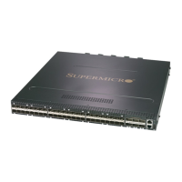
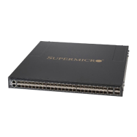
| Number of SFP+ Slots | 48 |
| Number of QSFP28 Ports | 6 |
| Product Type | Switch |
| Uplink Ports | 6 x 100G QSFP28 |
| Ethernet Technology | 10 Gigabit Ethernet, 100 Gigabit Ethernet |
| Height | 1.7" |
| Width | 17.3 in |
| Management | CLI, Web, SNMP |
| Operating Temperature | 0°C to 40 °C (32 °F to 104 °F) |