5-16
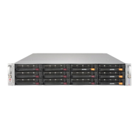
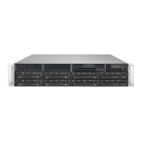
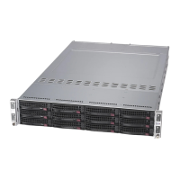
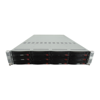
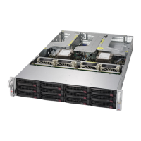
SUPERSERVER 6028U-T Series User's Manual
Overheat (OH)/Fan Fail/PWR Fail/
UID LED
Connect an LED cable to pins 7 and
8 of Front Control Panel to use the
Overheat/Fan Fail/Power Fail and
UID LED connections. The Red
LED on pin 8 provides warnings of
overheat, fan failure or power failure.
The Blue LED on pin 7 works as
the front panel UID LED indicator.
Refer to the table on the right for pin
OH/Fan Fail/ PWR Fail/Blue_
UID LED Pin Denitions (JF1)
7 Blue_UID LED
8 OH/Fan Fail/Power Fail
OH/Fan Fail/PWR Fail
LED Status (Red LED)
Normal
On Overheat
Flashing Fan Fail
Power Fail LED
The Power Fail LED connection
is located on pins 5 and 6 of JF1.
Refer to the table on the right for pin
PWR Fail LED
Pin Denitions (JF1)
5 3.3V
6 PWR Supply Fail
Reset Button
The Reset Button connection is
located on pins 3 and 4 of JF1. Attach
it to the hardware reset switch on the
computer case. Refer to the table on
Power Button
The Power Button connection is
located on pins 1 and 2 of JF1.
Momentarily contacting both pins will
as a suspend button (see the Power
Button Mode setting in BIOS). To turn
mode, depress the button for at least
4 seconds. Refer to the table on the
Reset Button
Pin Denitions (JF1)
3 Reset
4 Ground
Power Button
Pin Denitions (JF1)
1 Signal
2 Ground
 Loading...