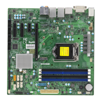
48
Super X11SCQ/-L User's Manual
+
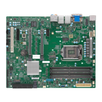
X11SCQ
REV:1.01
MAC CODE
BAR CODE
DESIGNED IN USA
BIOS
LICENSE
Intel
Q370/H310
JGP1
JSMB1
DIMMA1
DIMMB1
DIMMA2
DIMMB2
J23
COM3/4
COM5/6
MH12
MH11
MH9
CON1
JPW2
SP1
COM2
COM1
JSTBY1
JD1
FAN1
FAN3
FAN4
FAN2
JPT1
JAT1
JPME2
JWD1
JLED1
JPL2
JPAC1
JPL1
JPW1
JL1
I-SATA5
I-SATA2
I-SATA4
I-SATA1
I-SATA3
I-SATA0
JF1
JBT1
JSD1
JTPM1
J*
B3
LED3
LED1
EDP
CPU
AUDIO FP
USB4/5
USB6/7(3.1)
SLOT4
SLOT5
SLOT6
ON
PWR
X
LED
OH/FF
RST
NIC2 NIC1
HDD
LED
USB10/11(3.1)
LED
PWR
HD AUDIO
SLOT7
UNB NON-ECC DDR4 DIMM REQUIRED
ALWAYS POPULATE BLUE SOCKET FIRST
PCI-E M.2-M1
LAN2
USB2/3
USB8/9(3.1)
LAN1
HDMI/DP
DVI-D
CPU FAN
KB/MOUSE
USB0/1
J5
1. Standby Power
2. Onboard Power LED
1
2
Standby Power
The Standby Power header is located at JSTBY1 on the motherboard. Refer to the table
below for pin denitions.
Standby Power
Pin Denitions
Pin# Denition
1 +5V Standby
2 Ground
3 No Connection
Onboard Power LED
An onboard Power LED header is located at JLED1. This Power LED header is connected
to the Front Control Panel located at JF1 to indicate the status of the system power. See the
table below for pin denitions.
Onboard Power LED
Pin Denitions
Pins Denition
1 VCC
2 No Connection
3
Connection to
PWR LED on JF1
 Loading...
