37
Chapter 2: Installation
J7 J8
FAN4
JPWR2
JPWR1
JPL1
JPL3
I-SATA3
I-SATA2
JSD2
JSD1
JL1
LAN 1/3
LAN 2/4
USB 6/7
(3.0)
COM 1
JOH1
JUIDB1
DIMMB2
DIMMB1
DIMMA2
DIMMA1
J23
SP1
USB 2/3
JI2C2
JI2C1
JPB1
JPME2
JPG1
BAR CODE
MAC CODE
IPMI CODE
I-SGPIO2
I-SGPIO1
Intel PCH
USB 0/1
IPMI_LAN
VGA
LED BMC
COM2
JPL2
JPL4
JPI2C1
FAN1
FAN2
LED PWR
JSTBY1
JWD1
FAN3
FANA
JF1
USB 8/9
(3.0)
USB 10
(3.0)
USB 4/5
JTPM1
JBT1
JIPMB1
JD1
JBR1
PCH SLOT4 PCI-E 3.0 x4in x8
CPU SLOT5 PCI-E 3.0 x8
CPU SLOT6 PCI-E 3.0 x8in x16
BIOS
LICENSE
BMC
LE1
I-SATA7
I-SATA6
I-SATA5
I-SATA4
I-SATA1
I-SATA0
LE3
X11SSH-F/-LN4F
REV:1.01
Designed in the USA
BT1
CPU
2 3
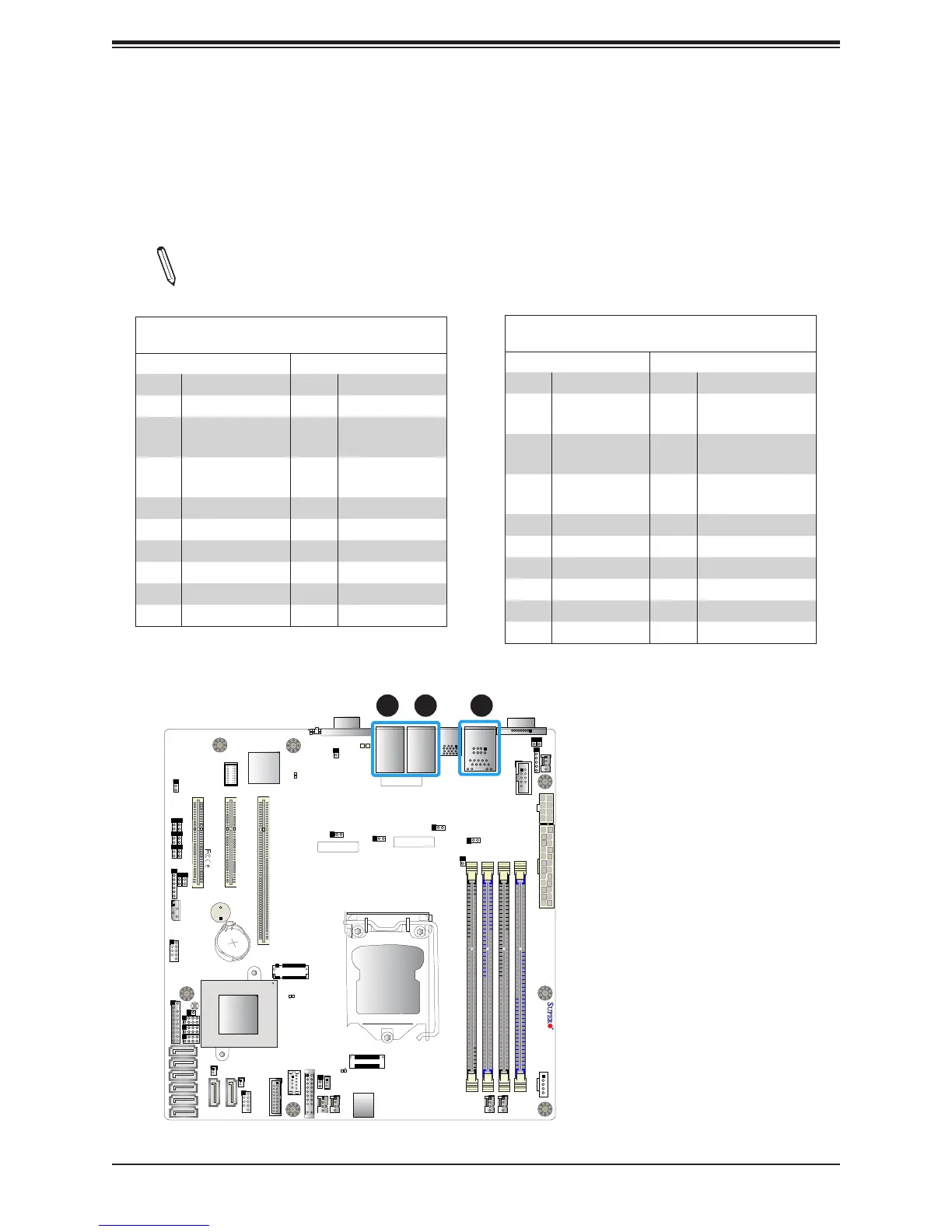
LAN Ports
Two Gigabit Ethernet ports (LAN1 and LAN2) are located on the I/O back panel on the
motherboard. In addition, a dedicated IPMI LAN is located above USB 0/1 ports on the back
panel. All of these ports accept RJ45 cables. Please refer to the LED Indicator section for
LAN LED information.
Note: The -LN4F board contains two additional Gigabit Ethernet ports (LAN3 and
LAN4) on top of LAN1 and LAN2, respectively.
LAN Ports 1-4
Pin Denition
Pin# Denition Pin# Denition
1 TD0- 11 P3V3_Dual
2 TD0+ 12 Act LED (Yellow)
3 TD1- 13
Link 1000 LED
(Amber)
4 TD1+ 14
Link 100 LED
(Green)
5 TD2- 15 GND
6 TD2+ 16 GND
7 TD3- 17 GND
8 TD3+ 18 GND
9 COMMCT
10 GND
IPMI_LAN
Pin Denition
Pin# Denition Pin# Denition
9 19 GND
10 TD0+ 20
Act LED
(Yellow)
11 TD0- 21
Link 100 LED
(Green)
12 TD1+ 22
Link 1000 LED
(Amber)
13 TD1- 23 SGND
14 TD2+ 24 SGND
15 TD2- 25 SGND
16 TD3+ 26 SGND
17 TD3-
18 GND
1
1. LAN1
2. LAN2
3. IPMI_LAN