48
X11SSH-F/-LN4F User Manual
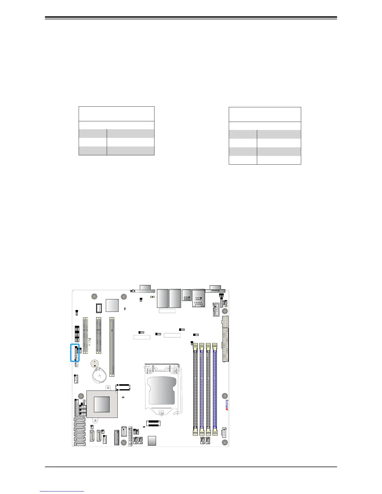
Power LED/Speaker
Pins 1-3 of JD1 are used for power LED indication, and pins 4-7 are for the speaker. Please
note that the speaker connector pins (4-7) are used with an external speaker. If you wish to
use the onboard speaker, you should close pins 6-7 with a cap. Refer to the tables below
for pin denitions.
PWR LED Connector
Pin Denitions
Pin Setting Denition
1 JD1_PIN1
2 FP_PWR_LED
3 FP_PWR_LED
Speaker Connector
Pin Denitions
Pin Setting Denition
4 P5V
5 Key
6 R_SPKPIN_N
7 R_SPKPIN
J7 J8
FAN4
JPWR2
JPWR1
JPL1
JPL3
I-SATA3
I-SATA2
JSD2
JSD1
JL1
LAN 1/3
LAN 2/4
USB 6/7
(3.0)
COM 1
JOH1
JUIDB1
DIMMB2
DIMMB1
DIMMA2
DIMMA1
J23
SP1
USB 2/3
JI2C2
JI2C1
JPB1
JPME2
JPG1
BAR CODE
MAC CODE
IPMI CODE
I-SGPIO2
I-SGPIO1
Intel PCH
USB 0/1
IPMI_LAN
VGA
LED BMC
COM2
JPL2
JPL4
JPI2C1
FAN1
FAN2
LED PWR
JSTBY1
JWD1
FAN3
FANA
JF1
USB 8/9
(3.0)
USB 10
(3.0)
USB 4/5
JTPM1
JBT1
JIPMB1
JD1
JBR1
PCH SLOT4 PCI-E 3.0 x4in x8
CPU SLOT5 PCI-E 3.0 x8
CPU SLOT6 PCI-E 3.0 x8in x16
BIOS
LICENSE
BMC
LE1
I-SATA7
I-SATA6
I-SATA5
I-SATA4
I-SATA1
I-SATA0
LE3
X11SSH-F/-LN4F
REV:1.01
Designed in the USA
BT1
CPU
1. Speaker Header