52
X11SSH-F/-LN4F User Manual
J7 J8
FAN4
JPWR2
JPWR1
JPL1
JPL3
I-SATA3
I-SATA2
JSD2
JSD1
JL1
LAN 1/3
LAN 2/4
USB 6/7
(3.0)
COM 1
JOH1
JUIDB1
DIMMB2
DIMMB1
DIMMA2
DIMMA1
J23
SP1
USB 2/3
JI2C2
JI2C1
JPB1
JPME2
JPG1
BAR CODE
MAC CODE
IPMI CODE
I-SGPIO2
I-SGPIO1
Intel PCH
USB 0/1
IPMI_LAN
VGA
LED BMC
COM2
JPL2
JPL4
JPI2C1
FAN1
FAN2
LED PWR
JSTBY1
JWD1
FAN3
FANA
JF1
USB 8/9
(3.0)
USB 10
(3.0)
USB 4/5
JTPM1
JBT1
JIPMB1
JD1
JBR1
PCH SLOT4 PCI-E 3.0 x4in x8
CPU SLOT5 PCI-E 3.0 x8
CPU SLOT6 PCI-E 3.0 x8in x16
BIOS
LICENSE
BMC
LE1
I-SATA7
I-SATA6
I-SATA5
I-SATA4
I-SATA1
I-SATA0
LE3
X11SSH-F/-LN4F
REV:1.01
Designed in the USA
BT1
CPU
Power SMB (I
2
C) Header
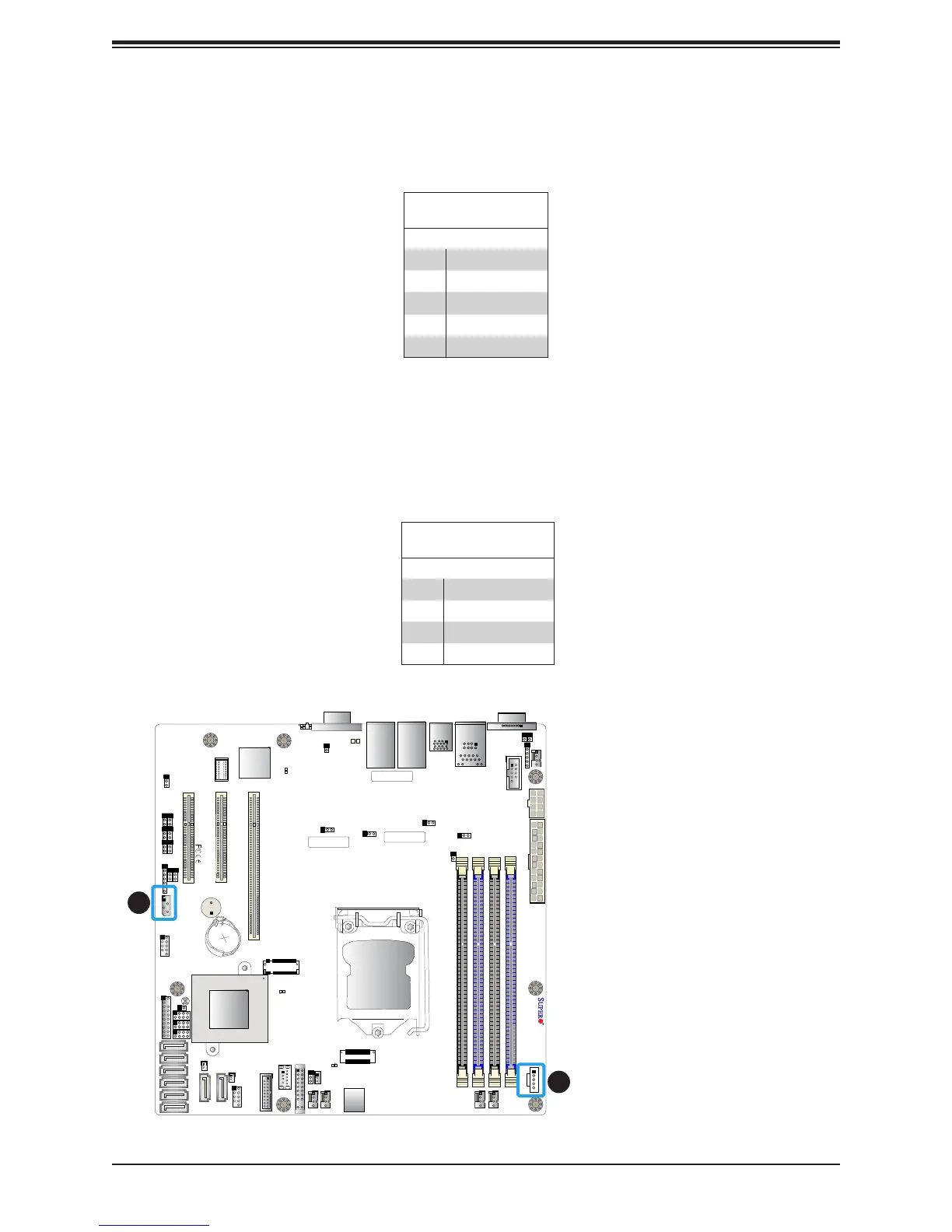
The Power System Management Bus (I
2
C) connector (JPI
2
C1) monitors the power supply,
fan, and system temperatures. Refer to the table below for pin denitions.
Power SMB Header
Pin Denitions
Pin# Denition
1 Clock
2 Data
3 PMBUS_Alert
4 Ground
5 +3.3V
4-pin BMC External I
2
C Header
A System Management Bus header for IPMI 2.0 is located at JIPMB1. Connect the appropriate
cable here to use the IPMB I
2
C connection on your system. Refer to the table below for pin
denitions.
External I
2
C Header
Pin Denitions
Pin# Denition
1 Data
2 GND
3 Clock
4 NC
1
2
1. Power SMB Header
2. BMC External Header