11
Chapter 1: Introduction
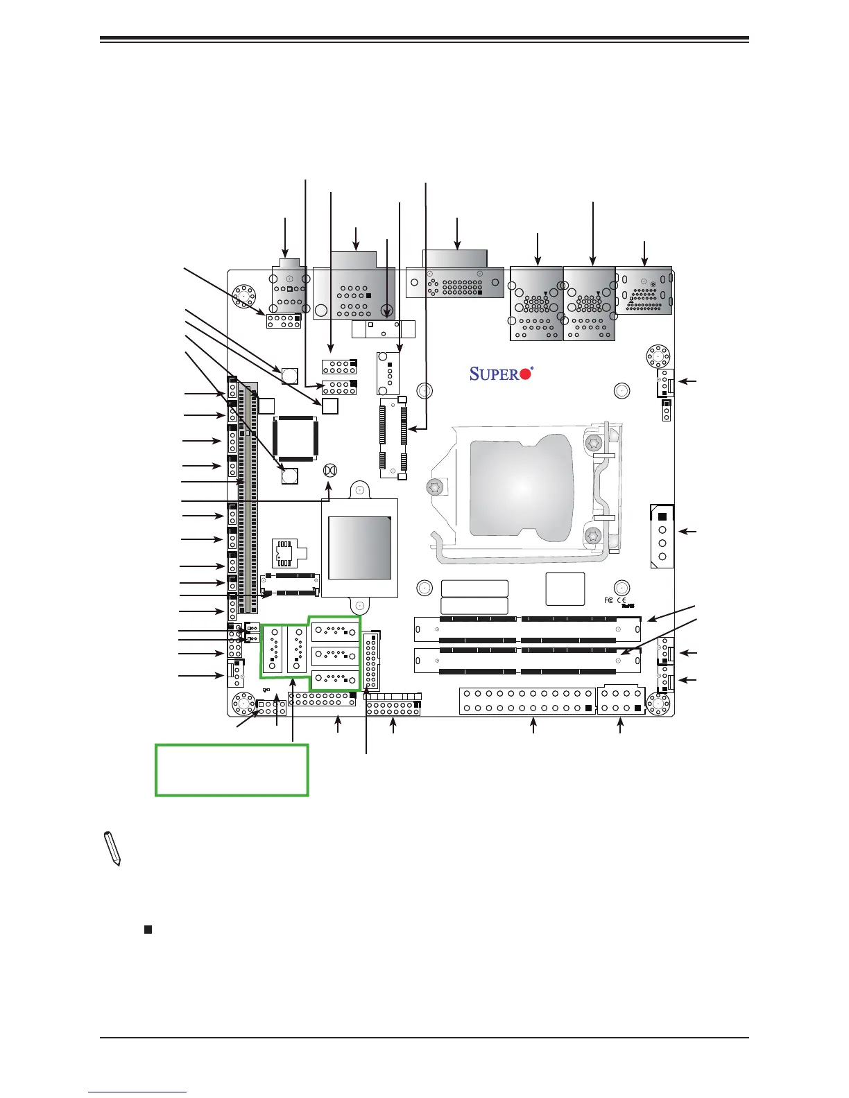
Quick Reference
Notes:
• See Chapter 2 for detailed information on jumpers, I/O ports, and JF1 front panel con-
nections.
• " " indicates the location of Pin 1.
• Jumpers/LED indicators not indicated are used for testing only.
• Use only the correct type of onboard CMOS battery as specied by the manufacturer. Do
not install the onboard battery upside down to avoid possible explosion.
SINGLE-LINK
m-PCIE(F/H)
M.2
HD
AUDIO
CPU SLOT1 PCI-E 3.0 X16
PWR
LED
NICHDD
LED
NIC
21
OH/FF
USB11/12
USB7/8
RSTX
PWR
JF1
ON
(3.0)
USB5/6
USB9
COM1/2
DVI-I
DIMMA1
DIMMB1
UNB NON-ECC DDR4 DIMM REQUIRED
LAN2
USB3/4(3.0)
REV:
X11SSV-Q
1.01
USB1/2(3.0)
LAN1
CPU
DESIGNED IN USA
DP
HDMI
MAC CODE
BAR CODE
BIOS
LICENSE
A
C
1
JGPIO1
JI2C1
JI2C2
JWD1
JVR1
JPAC1
JPME2
JPUSB1
JSMB1
JD1
JL1
JSD1
JSD2
JTPM1
SRW6
SRW5
I-SATA0
I-SATA1
I-SATA4
I-SATA3
I-SATA2
SRW2
SRW1
JBT1
LED1
JF1
BT1
JPW1
JPW2
JP1
FAN4
FAN2
FAN3
FAN1
J3
I-SGPIO1
COM1
COM2
HD AUDIO
DVI-I
LAN2
USB3/4 (3.0)
LAN1
USB1/2 (3.0)
HDMI/DP
BT1
USB11/12
USB7/8
JI2C1
JI2C2
JSMB1
JWD1
JPAC1
JPME2
JPUSB1
JL1
JD1
JSD1
JSD2
JGPIO1
FAN4
JTPM1
LED1
JF1
USB5/6 (3.0)
I-SATA0 I-SATA1
I-SATA4
I-SATA3
I-SATA2
JPW1
JPW2
FAN3
FAN2
DIMMA1
DIMMB1
JP1
FAN1
USB9
M.2
JBT1
m-PCIE(F/H)
SRW5
SRW1
SRW6
SRW2
J3
SLOT1
I-SGPIO1
 Loading...


