49
Chapter 2: Installation
M.2 Sockets
M.2 sockets are designed for devices such as memory cards, wireless adapters, etc. These
devices must conform to the PCI-E M.2 specications (formerly known as NGFF).
Note: PCIE M.2-M1 and PCIE M.2-M2 support RAID 0 and RAID 1.
SATA Ports
Four Serial ATA (SATA) 3.0 connectors (I-SATA 0~3) are supported on the motherboard. These
I-SATA 3.0 ports are supported by the Intel W480 PCH chip (supports RAID 0, 1, 5, and 10).
SATA ports provide serial-link signal connections, which are faster than the connections of
Parallel ATA. Refer to the table below for pin denitions.
Note: For more information on the SATA HostRAID conguration, please refer to the
Intel SATA HostRAID user's guide posted on our website at https://www.supermicro.
com/support/manuals/.
SATA 3.0 Connectors
Pin Denitions
Pin# Denition
1 Ground
2 SATA_TXP
3 SATA_TXN
4 Ground
5 SATA_RXN
6 SATA_RXP
7 Ground
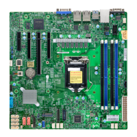
1. PCIE M.2-M1
2. PCIE M.2-M2
3. I-SATA0 / I-SATA01
4. I-SATA2 / I-SATA03
IPMI CODE
X12SCA-F
REV:1.01
MAC CODE
MAC CODE
BAR CODE
DESIGNED IN USA
BIOS LICENSE
B3
JD1
JPW2
JBT1
CPU_FAN2
CPU_FAN1
SYS_FAN1
SYS_FAN2
BMC_HB_LED
JSD1
JF1
JTPM1
JPW1
SP1
JPI2C1
JL1
COM1
LED4
CATERR_LED
PWR_LED
JPL1
JPAC1
JPG1
JPL2
JWD1
JPME2
PCH
BMC
USB3.2Gen2
USB10
USB3.2 Gen2
12V_PUMP_PWR1
HDMI
DP
DIMMA1
DIMMA2
DIMMB1
DIMMB2
VGA
DVI
USB3.2Gen2 USB3.2Gen1
LAN1
USB6/7
LAN2
USB2/3
IPMI_LAN
USB8/9
AUDIO
USB3.2 Gen1
UID
USB4/5
CPU SLOT6 PCI-E 3.0 X16
CPU SLOT4 PCI-E 3.0 X8 (IN X16)
I-SATA0
I-SATA1
I-SATA2
I-SATA3
PCH SLOT2 PCI-E 3.0 X4
JSTBY1
SLOT1 PCI 33MHZ
AUDIO FP
USB0/1
PCI-E_M.2-M1
PCI-E_M.2-M2
4 3
1
2

 Loading...

