55
Chapter 2: Installation
Audio Enable/Disable
JPAC1 allows you to enable or disable the onboard audio support. The default position is on
pins 1 and 2 to enable onboard audio connections. Refer to the table below for jumper settings.
Audio Enable/Disable
Jumpers Settings
Jumper Setting Denition
Pins 1-2 Enabled (Default)
Pins 2-3 Disabled
Manufacturing Mode
Close pins 2 and 3 of Jumper JPME2 to bypass SPI ash security and force the system to
operate in Manufacturing Mode, allowing the user to ash the system rmware from a host
server for system setting modications. Refer to the table below for jumper settings.
Manufacture Mode
Jumpers Settings
Jumper Setting Denition
Pins 1-2 Enabled (Default)
Pins 2-3 Manufacturing Mode
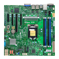
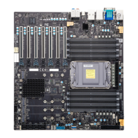
1. JPAC1
2. JPME2
IPMI CODE
X12SCA-F
REV:1.01
MAC CODE
MAC CODE
BAR CODE
DESIGNED IN USA
BIOS LICENSE
B3
JD1
JPW2
JBT1
CPU_FAN2
CPU_FAN1
SYS_FAN1
SYS_FAN2
BMC_HB_LED
JSD1
JF1
JTPM1
JPW1
SP1
JPI2C1
JL1
COM1
LED4
CATERR_LED
PWR_LED
JPL1
JPAC1
JPG1
JPL2
JWD1
JPME2
PCH
BMC
USB3.2Gen2
USB10
USB3.2 Gen2
12V_PUMP_PWR1
HDMI
DP
DIMMA1
DIMMA2
DIMMB1
DIMMB2
VGA
DVI
USB3.2Gen2 USB3.2Gen1
LAN1
USB6/7
LAN2
USB2/3
IPMI_LAN
USB8/9
AUDIO
USB3.2 Gen1
UID
USB4/5
CPU SLOT6 PCI-E 3.0 X16
CPU SLOT4 PCI-E 3.0 X8 (IN X16)
I-SATA0
I-SATA1
I-SATA2
I-SATA3
PCH SLOT2 PCI-E 3.0 X4
JSTBY1
SLOT1 PCI 33MHZ
AUDIO FP
USB0/1
PCI-E_M.2-M1
PCI-E_M.2-M2
2
1

 Loading...

