47
Chapter 2: Installation
BIOS
LICENSE
1
BAR CODE
IPMI CODE
MAC CODE
SAN MAC
DESIGNED IN USA
X12SPW-TF/F
REV: 2.00
JNCSI1
S-SGPIO1
JBT1
JPWR2
JSD2
JSD1
S-SATA1
S-SATA0
JSTBY1
JRK1
JPWR3
JPWR1
JF1
JVRM2
JVRM1
JPFR3
JPFR2
JPFR1
JL1
JD1
JPRG1
JWD1
JP4
FAN6
FAN7
FAN4
FAN3
FAN5
FAN1
BT1
NVME0/1
NVME2/3
MH16
MH15
JPI2C1
JIPMB1
JNVI2C
JI2C_EXP1
MH4
MH6
MH1
MH9
MH5
MH3
MH2
JPME1
JPL2
JMP2
JMP1
JPL1
JPL3
SXB2: PCIe 4.0 X16
SXB1A
SXB1B: PCIe 4.0 X16 + X16
SXB1C
COM2
I-SATA4~7
M.2-H
COM1
DIMMG1
DIMMH1
DIMME1
DIMMF1
DIMMA1
DIMMB1
DIMMD1
DIMMC1
CPU
USB6/7(3.0)
USB4/5 (3.0)
USB2/3
LAN2
LAN1
CMOS CLEAR
I-SATA0~3
TPM/PORT80
UID-SW
UID-LED
VGA
USB0/1
IPMI_LAN
USB8(3.0)
LE3
LEDBMC
LE4
FAN2
BMC
AST2600
PCH
621A
Required Connection
8-pin Power
Pin Denitions
Pin# Denition
1 - 4 Ground
5 - 8 P12V (12V Power)
8-Pin Power Connector
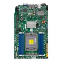
JPWR1 is an 8-pin 12V DC power input for the CPU that must be connected to the power
supply. Refer to the table below for pin denitions.
1
Important: To provide adequate power supply to the motherboard, be sure to connect
the 24-pin ATX PWR, the 8-pin PWR, and 4-pin PWR connectors to the power sup-
ply. Failure to do so may void the manufacturer warranty on your power supply and
motherboard.
1. 4-Pin PWR
2. 8-Pin PWR
Required Connection
4-pin Power
Pin Denitions
Pin# Denition
1 - 2 Ground
3 - 4 P12V (12V Power)
4-Pin Power Connector
JPWR2 is an 4-pin 12V DC power input for the CPU that must be connected to the power
supply. Refer to the table below for pin denitions.
2
 Loading...
