55
Chapter 2: Installation
BIOS
LICENSE
1
BAR CODE
IPMI CODE
MAC CODE
SAN MAC
DESIGNED IN USA
X12SPW-TF/F
REV: 2.00
JNCSI1
S-SGPIO1
JBT1
JPWR2
JSD2
JSD1
S-SATA1
S-SATA0
JSTBY1
JRK1
JPWR3
JPWR1
JF1
JVRM2
JVRM1
JPFR3
JPFR2
JPFR1
JL1
JD1
JPRG1
JWD1
JP4
FAN6
FAN7
FAN4
FAN3
FAN5
FAN1
BT1
NVME0/1
NVME2/3
MH16
MH15
JPI2C1
JIPMB1
JNVI2C
JI2C_EXP1
MH4
MH6
MH1
MH9
MH5
MH3
MH2
JPME1
JPL2
JMP2
JMP1
JPL1
JPL3
SXB2: PCIe 4.0 X16
SXB1A
SXB1B: PCIe 4.0 X16 + X16
SXB1C
COM2
I-SATA4~7
M.2-H
COM1
DIMMG1
DIMMH1
DIMME1
DIMMF1
DIMMA1
DIMMB1
DIMMD1
DIMMC1
CPU
USB6/7(3.0)
USB4/5 (3.0)
USB2/3
LAN2
LAN1
CMOS CLEAR
I-SATA0~3
TPM/PORT80
UID-SW
UID-LED
VGA
USB0/1
IPMI_LAN
USB8(3.0)
LE3
LEDBMC
LE4
FAN2
BMC
AST2600
PCH
621A
SATA Ports
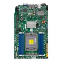
Eight SATA 3.0 ports are located on the motherboard supported by the chipset. These SATA
ports support RAID 0, 1, 5, and 10. In addition, there are also two S-SATA ports (S-SATA0,
S-SATA1) that include SATA DOM power. SATA ports provide serial-link signal connections,
which are faster than the connections of Parallel ATA. Refer to the tables below for pin
denitions.
Note: For more information on the SATA HostRAID conguration, please refer to the
Intel SATA HostRAID user's guide posted on our website at http://www.supermicro.com.
5
6
1. I-SATA0
2. I-SATA1
3. I-SATA2
4. I-SATA3
5. I-SATA4
6. I-SATA5
7. I-SATA6
8. I-SATA7
9. S-SATA0
10. S-SATA1
11. M.2 Slot
4
3
8
7
M.2 Slot
The motherboard has one M.2 slot. M.2 was formerly known as Next Generation Form Factor
(NGFF) and serves to replace mini PCIe. M.2 allows for a variety of card sizes, increased
functionality, and spatial eciency. The M.2 socket on the motherboard supports PCIe 3.0
x4/SATA3 SSD cards in the 2280 and 22110 form factors.
9
1
2
11
10
 Loading...
