2-28
X10DRi/X10DRi-T Motherboard User’s Manual
JPI2C1
JPWR1
JPWR2
JOH1
JL1
JSD1
JSTBY1
JTPM1
JPB1
JWD1
JVRM1
JI2C2
JPME2
JI2C1
SP1
JIPMB1
LE2
FAN4
FAN2
FAN3
FAN1
FANB
S-SATA2
MAC CODE
BAR CODE
S-SATA3
S-SATA0
S-SATA1
Fan5
T-SGPIO3
USB2/3
IPMI_LAN
UID
JBT1
T-SGPIO2
T-SGPIO1
I-SATA1
I-SATA0
I-SATA3
I-SATA5
I-SATA4
COM2
CPU1 SLOT1 PCI-E 3.0 X8
CPU1 SLOT2 PCI-E 3.0 X16
CPU1 SLOT3 PCI-E 3.0 X8
CPU2 SLOT4 PCI-E 3.0 X16
CPU2 SLOT5 PCI-E 3.0 X8
CPU2 SLOT6 PCI-E 3.0 X16
P1 DIMMC2
P1 DIMMC1
P2 DIMME1
P2 DIMME2
P1 DIMMD1
P1 DIMMD2
P2 DIMMF1
P2 DIMMF2
VGA
P1 DIMMB2
P2 DIMMH2
P1 DIMMA1
P1 DIMMA2
P2 DIMMG1
P2 DIMMH1
P2 DIMMG2
LAN2
COM1
LAN1
USB0/1
LE1
Fan6
LEDM1
BIOS
JD1
USB4/5
I-SATA2
FANA
JPG1
JPL1
JF1
P1 DIMMB1
FPCTRL
Battery
X10DRi-(T)
Rev. 1.02
Intel PCH
LAN CTRL
BMC
BMC FW
J24
VGA/BMC
Memory
(2.0)
(USB2.0)
(USB2.0)
CLOSE 1st
OPEN 1st
CLOSE 1st
OPEN 1st
USB6/7(3.0)
USB8/9
(3.0)
USB10 (3.0)
CPU2
CPU1
JUIDB1
JVRM2
J23
J25
J27
J26
J-USB3-1AA
JSD2
B
A
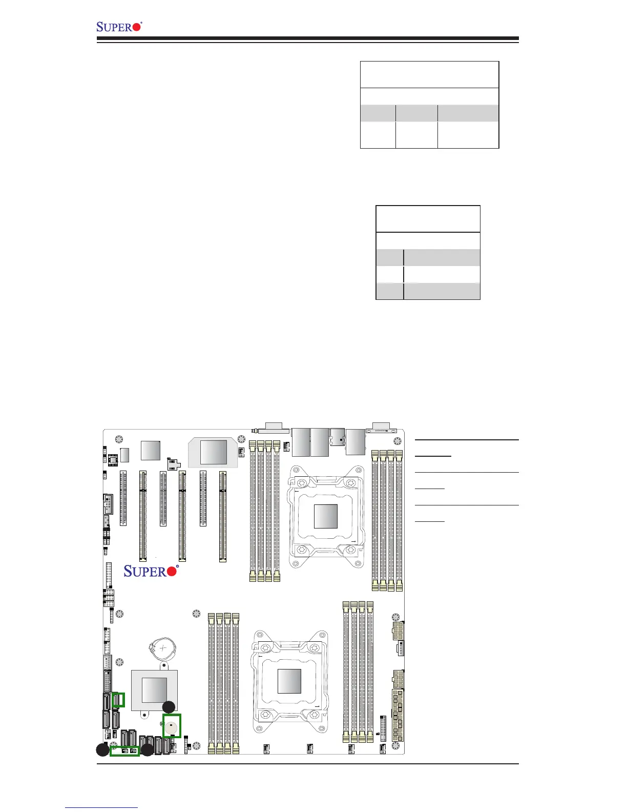
A. Internal Speaker
(Buzzer)
B. SATA DOM PWR
(JSD1)
C. SATA DOM PWR
(JSD2)
Internal Speaker
The Internal Speaker (SP1) can be used to
provide audible indications for various beep
codes. See the table on the right for pin deni-
tions. Refer to the layout below for the location
of the Internal Buzzer.
Internal Buzzer
Pin Denition
Pin# Denitions
Pin 1 Pos. (+) Beep In
Pin 2 Neg. (-) Alarm
Speaker
C
Powered SATA DOM (SuperDOM)
Connectors
Two powered SATADOM (Device-on-Module)
connectors are located at JSD1/JSD2 on
the motherboard. These connectors, colored
in yellow, are used with Supermicro Super-
DOMs, which have power-pins built in and do
not require separate external power cables.
These connectors are also back-compatible
with non-Supermicro SATADOMs that require
external power.
SuperDOM Connector
Pin Denitions
Pin# Denition
1 +5V
2 Ground
3 Ground