396-3815Y1 SureFire PumpRight for Raven RCM 35 Revised 12/04/2019
Floating Ball Flow Indicators
E
Installation
Overview
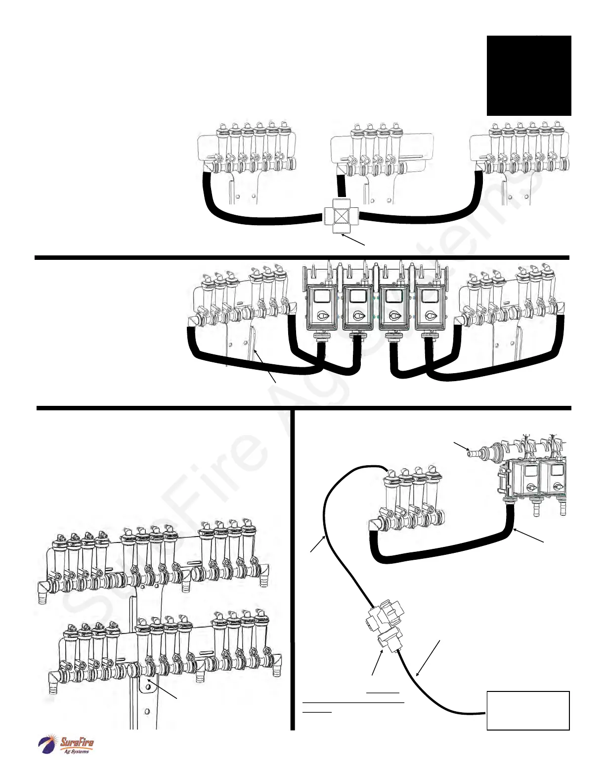
Flow Indicators are extremely flexible and can be mounted in hundreds of different
configurations on various types of liquid application equipment. This page is to give you
some ideas and let you customize the installation for what works best on your equipment.
From Flowmeter Outlet
16 Row
Split 6 - 4 - 6
This configuration
works well on a 16 row front
fold planter. Each flow
indicator manifold is shown fed
by a cross in a single section
installation. Each manifold
could be fed by a section valve
if desired.
12 Row
Split 3 - 3 - 3 - 3
Shown here is a 12
row with four 3 row sections
controlled by four section
valves. Note each 6 row T-
Bracket can hold two
separate 3 row manifolds.
A 4 section 24 row
could be similar with four 6 row
manifolds on two large T-Brackets.
12 Row Dual Product
Product 1 Split 4 - 4 - 4 / Product 2 Split 4 - 4 - 4
In this case each manifold would be fed by a
section valve. There would be 6 total section
valves (3 sections X 2 products). Most often one
set (top) of flow indicators would be Full Flow for
high rate fertilizer and 2nd set (bottom) would be
Low Flow for starter.
Dual Product Add-on Kit
515-1005 12 Row
515-1006 6 Row
NOTE: Another option is the flange can face forward so the
T-Bracket could be mounted on the front side of a bar.
General Plumbing Guidelines
Fertilizer Opener,
Seed Firmer, SS
Tube, etc.
From Flowmeter Outlet
Minimum 3/4” hose
used to feed each manifold.
Length of this hose can vary
significantly.
This is usually 1/4” OD tubing
or 3/8” hose. Typical length is
1-4’ with check valves placed
on each row that distance from
ground.
This is
usually
1/4” OD
tubing or 3/8”
hose. Maxi-
mum recom-
mended length
is 20 feet and
lengths do not
need to be
equal.
Check valve is mounted
near each row. 1/4” turn
cap is always check valve
outlet. Colored disc orifice
can be placed under cap.
Product 1 on top
Product 2 on bottom