AN650/AK7 (’07-MODEL) 17
4) Remove the front panel. (#AN650K3 9-8)
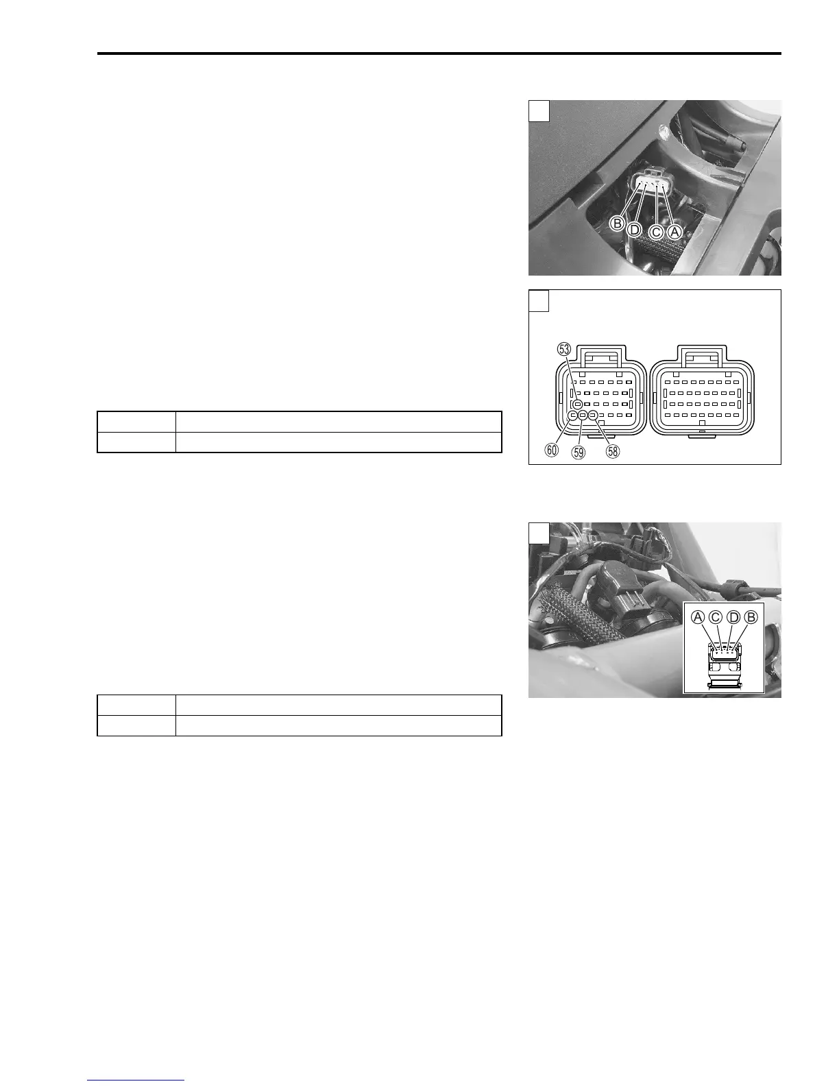
5) Disconnect the ISC valve coupler and ECM couplers.
6) Check the continuity between terminals
A (B/Lg) and
m, ter-
minals
B (P/W) and
t, terminals
C (G) and
s, terminals
D
(W/B) and
r.
$ ISC valve lead wire continuity: Continuity (%)
! 09900-25008: Multi-circuit tester set
09900-25009: Needle pointed probe set
& Tester knob indication: Continuity test (%)
Is the continuity OK?
7) After repairing the trouble, clear the DTC using SDS tool.
(Refer to the SDS operation manual for further details.)
Step 2
1) Remove the front box. (#AN650K3 9-18)
2) Measure the resistance between terminals
A and
B, termi-
nals
C and
D.
$ ISC valve resistance: Approx. 80
Ω
at 25 °C (77 °F)
(Terminal
A – Terminal
B)
(Terminal
C – Terminal
D)
Is the resistance OK?
3) After repairing the trouble, clear the DTC using SDS tool.
(Refer to the SDS operation manual for further details.)
YES Go to Step 2.
NO Y, B/Lg, P/W, G or W/B wire open.
YES If wire is OK, intermittent trouble or faulty ECM.
NO Replace the ISC valve with a new one.
1
ECM coupler (Harness side)
SAMPLE
 Loading...


