9
MOTOR MOUNTING
Suzuki strongly recommends that you have
your outboard motor, controls and gauges
installed by an authorized Suzuki Marine
Dealer. He has the tools, the facilities and the
know-how.
8
WARNING
Overpowering your boat can be hazardous.
Excessive horsepower will have an adverse
effect on hull safety and may cause operating/
handling difficulties. The boat may also sus-
tain stress and hull damage.
Never install an outboard motor with horse-
power exceeding the manufacturer’s recom-
mended maximum horsepower listed on the
boat’s “Certification Plate”. Contact your
authorized Suzuki marine dealer if you are
unable to locate the hull “Certificate Plate”.
8
WARNING
Failure to have your outboard motor and asso-
ciated controls and gauges properly installed
can result in personal injury or damage.
Suzuki strongly recommends that you have
your outboard motor, controls and gauges
installed by your authorized Suzuki marine
dealer. He has the tools, the facilities, and the
know-how to do the job correctly.
SELECTION OF LOWER UNIT ROTATION
Lower unit of this product can be used for both
regular rotation or counter rotation without
changing itself.
The motor will be shipped as regular rotation
specification from the factory.
To change the rotation from regular rotation to
counter, the rotation select connector located
near the starter motor should be changed from
the original one to the optional counter select
one.
To return it to regular rotation, use the original
connector again.
Please contact your authorized Suzuki Marine
Dealer for details.
NOTE:
• The selection of lower unit rotation closely
relates to the selection of the propeller type.
Confirm the lower unit rotation of the motor
before installing the propeller.
For propeller type selection, refer to the sec-
tion of “IDENTIFICATION OF LOWER UNIT
ROTATION AND PROPELLER TYPE
SELECTION”.
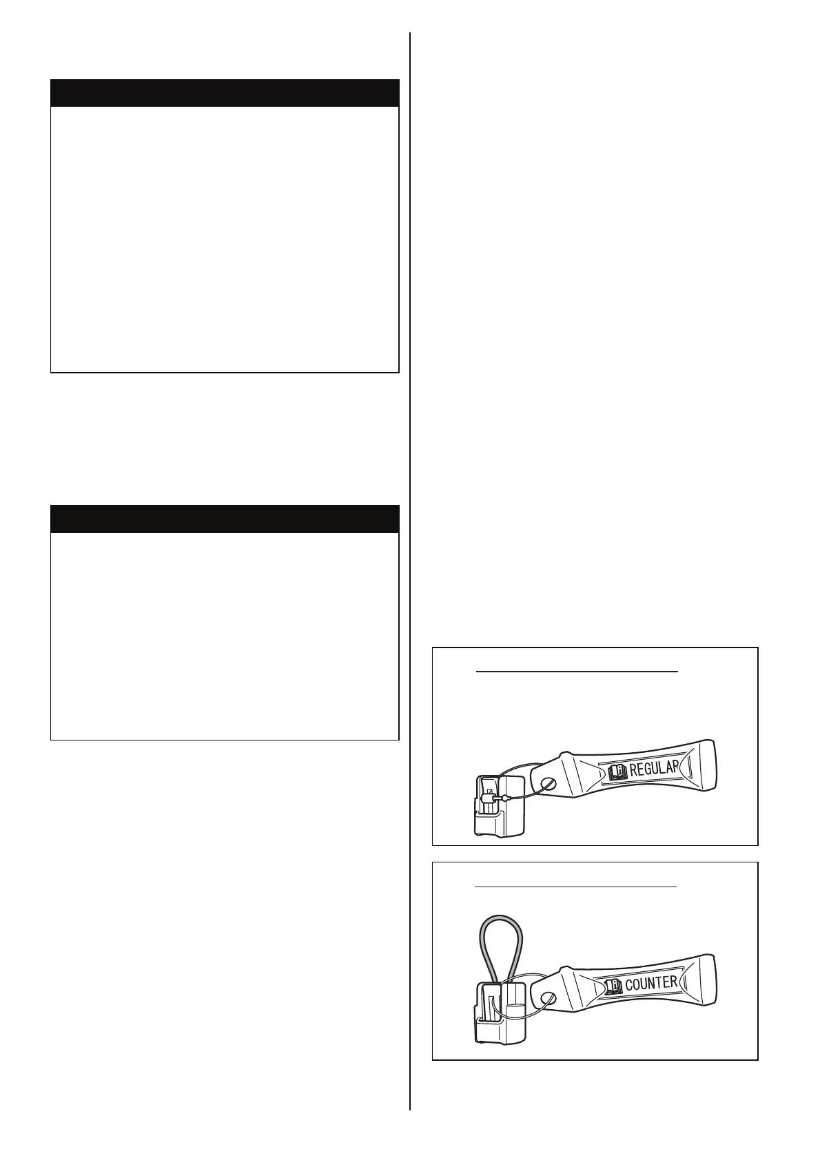
• When the rotation select connector
1 is
replaced, fix it onto the rectifier & regulator
harness 3 using the clamp 2 as shown in
the figure.
Regular select connector
Counter select connector