MOTORCYCLE
DATE:
Jul. 27, 2007
PAGE:
1
OF
14
SUBJECT:
NOTICE OF SET-UP MANUAL
APPLICABLE MODEL:
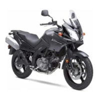
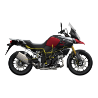
DL650AK8
EFFECTIVE ENGINE OR FRAME NO.:
REFERENCE:
This bulletin is to inform you of set-up procedures of DL650AK8.
Please inform your dealers of this notice.
DL650AK8 Set-Up Manual will not be issued because the set-up procedures for this model remain
unchanged from DL650K4 except the differences described below.
To set-up DL650AK8, please use the DL650K4 Set-Up Manual and this Service Bulletin.
DIFFERENCE BETWEEN DL650K4 AND DL650AK8
DL650K4 Set-Up Manual: 99505-01124-011
1. LOCATION OF PARTS [Page: 2, 3, 4]
Item Part Name Q’ty Remarks
A
Windscreen 1
Screw 4 5 × 20 mm
Collared spacer 4 OD:14.0 ID:5.5 T:5.0
Rubber cushion (with nut) 4 5 mm L:17.0
B
Windscreen cover 2
Tapping screw 2 5 × 16 mm
C
Handlebars assembly 1
Clamp 2
Allen bolt 4 8 × 30 mm
Burring washer 4 OD:13.0 ID:8.5
Plastic cap 4
OD11.0
For handlebar clamp
bolt
Screw 1
5 × 25 mm
For left switch
Screw 1
5 × 40 mm
For left switch
Screw 1
5 × 30 mm
For throttle assembly
Strap 2 L:140
Clutch lever cover 1
Item Part Name Q’ty Remarks
D
Handlebar balancer weight 1 Right
Screw 1 6 × 105 mm
Flange rubber cushion 1 L:34.0
Spacer 1 L:50.0
Spacer 1 OD:16.0 ID:6.5 T:4.0
Rubber cushion 1 L:15.0
Spacer nut 1 6 mm
E Rear view mirror 2 Right and Left
F Flange bolt 1
10 × 25 mm for
front brake caliper
G Front wheel assembly 1
H Helmet holder wire 2
I Washer 2 OD:13.0 ID:6.5
J Warning label set 7
For
E-19 CC selection
K Warning label set 4
For
E-19 CD selection
L
Battery electrolyte
container
1
MOwner’s manual set 1
N
Holder 1
For front brake
master cylinder
Flange bolt 2 6 × 22 mm
OD : Outside diameter (mm)
ID : Inside diameter (mm)
L : Length (mm)
T : Thickness (mm)
T
L
OD ID
NOTE:
The parts shown as Item J and K in the above table are supplied for limited markets.
Use washers of Item I for mounting the license plate.
Please hand over the parts shown as Items H and M in the above table to your customer together with
motorcycle.