ANTILOCK BRAKE SYSTEM (ABS) 5E2-17
Table-C ABS Warning Lamp Circuit Check – The Lamp Flashes Continuously
While Ignition Switch Is ON
CIRCUIT DESCRIPTION
When diagnosis switch terminal is shorted or connected to the ground with ignition switch ON, diagnosis trouble
code (DTC) is indicated by flashing of ABS warning lamp only in the following cases.
• Normal DTC (12) is indicated if no malfunction DTC is detected in the ABS.
• A history malfunction DTC is indicated by flashing of the lamp if a current malfunction DTC is not detected at
that point although a history malfunction DTC is stored in memory.
INSPECTION
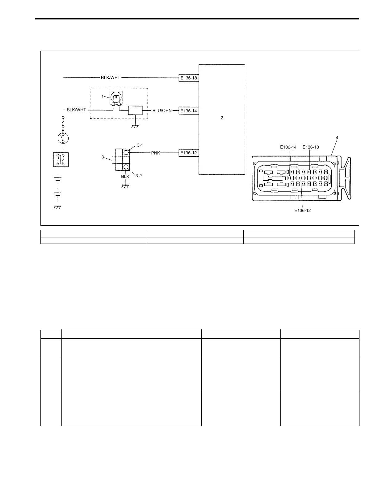
1. ABS warning lamp in combination meter 3. Diagnosis monitor coupler 3-2. Diagnosis ground terminal
2. ABS hydraulic unit/control module assembly 3-1. Diagnosis switch terminal 4. ABS hydraulic unit/control module connector
Step Action Yes No
1 Is diagnosis switch terminal connected to
ground via service wire?
Go to Step 3. Go to Step 2.
2 1) Ignition switch ON.
2) Measure voltage between diagnosis switch
terminal and ground.
Is it 10 – 14 V?
Substitute a known-good
ABS hydraulic unit/con-
trol module assembly and
recheck.
“PNK” wire circuit shorted
to ground.
3 1) Ignition switch ON.
2) Does flashing of ABS warning lamp indicate
DTC?
Go to Step 7 of “ABS
DIAGNOSTIC FLOW
TABLE” in this section.
Substitute a known-good
ABS hydraulic unit/con-
trol module assembly and
recheck.

 Loading...


