Automatic Transmission/Transaxle: 5A-63
DTC P1723 Range Select Switch Malfunction
S5JB0A5104056
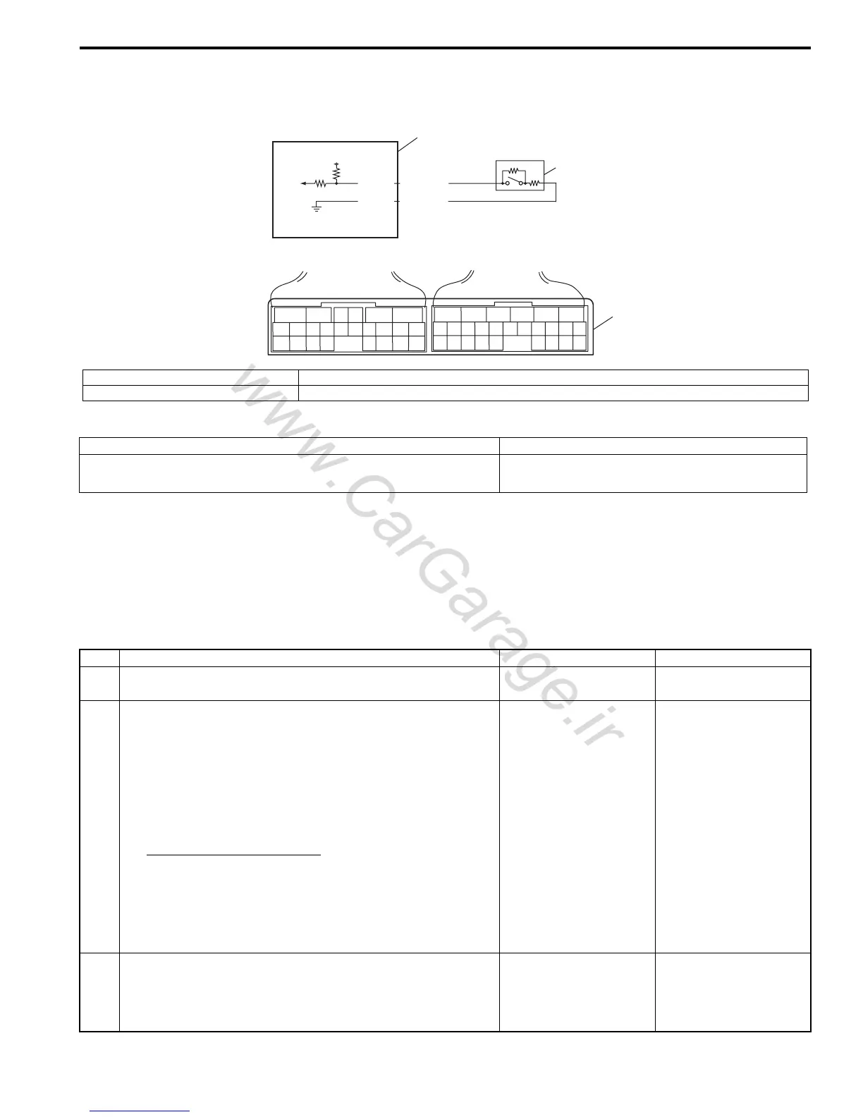
Wiring Diagram
DTC Detecting Condition and Trouble Area
DTC Confirmation Procedure
1) Connect scan tool to DLC with ignition switch OFF.
2) Clear DTCs in TCM and ECM memories by using scan tool.
3) Start engine and run it for 20 sec. or more.
4) Check DTC, pending DTC and freeze-frame data.
DTC Troubleshooting
5V
2
1
3
65
16 15 14 13 12 11
43
24 23 2122
10 9 8 7
21
1920 18 17
E92
17 16
26 25
15 14
65 342
13 12
23 2224
11 10 9
21 20 19
87
18
1
E93
E92-20
E92-10
YEL/RED
YEL/BLK
I5JB0A510001-01
1. “3” position switch 3. Terminal arrangement of TCM connector (viewed from harness side)
2. TCM
DTC Detecting Condition Trouble Area
“3” position switch signal is inputted out of specified value.
(1 driving cycle detection logic)
• “3” position switch or its circuit malfunction
•TCM
Step Action Yes No
1 Was “A/T System Check” performed? Go to Step 2. Go to “A/T System
Check: ”.
2 Check “3” position switch circuit
1) Disconnect TCM connector with ignition switch OFF.
2) Check for proper connection to “3” position switch at
“E92-10” and “E92-20” terminals.
3) If OK, check resistance of switch circuit between
terminals “E92-10” and “E92-20” of disconnected
harness side TCM connector.
“3” position switch circuit
Shift selector lever to “P”, “N” or “D” range: 3.96 –
4.04 kΩ
Shift selector lever to “R”, “3”, “2” or “L” range: 0.99
– 1.01 kΩ
Is result as specified?
Intermittent trouble or
faulty TCM. Check for
intermittent trouble
referring to “Intermittent
and Poor Connection
Inspection: in Section
00”. If OK, substitute a
known-good TCM and
recheck.
Go to Step 3.
3 Check “3” position switch
Check “3” position switch referring to ““3” Position Switch
Inspection: ”.
Is result as specified?
Replace “3” position
switch.
“3” position switch
circuit is malfunction.

 Loading...


