
T
tiffanytorresJul 27, 2025
Why does the battery run down quickly on my Suzuki GSX1200 1999 Motorcycle?
- MMrs. Kelly JamesJul 27, 2025
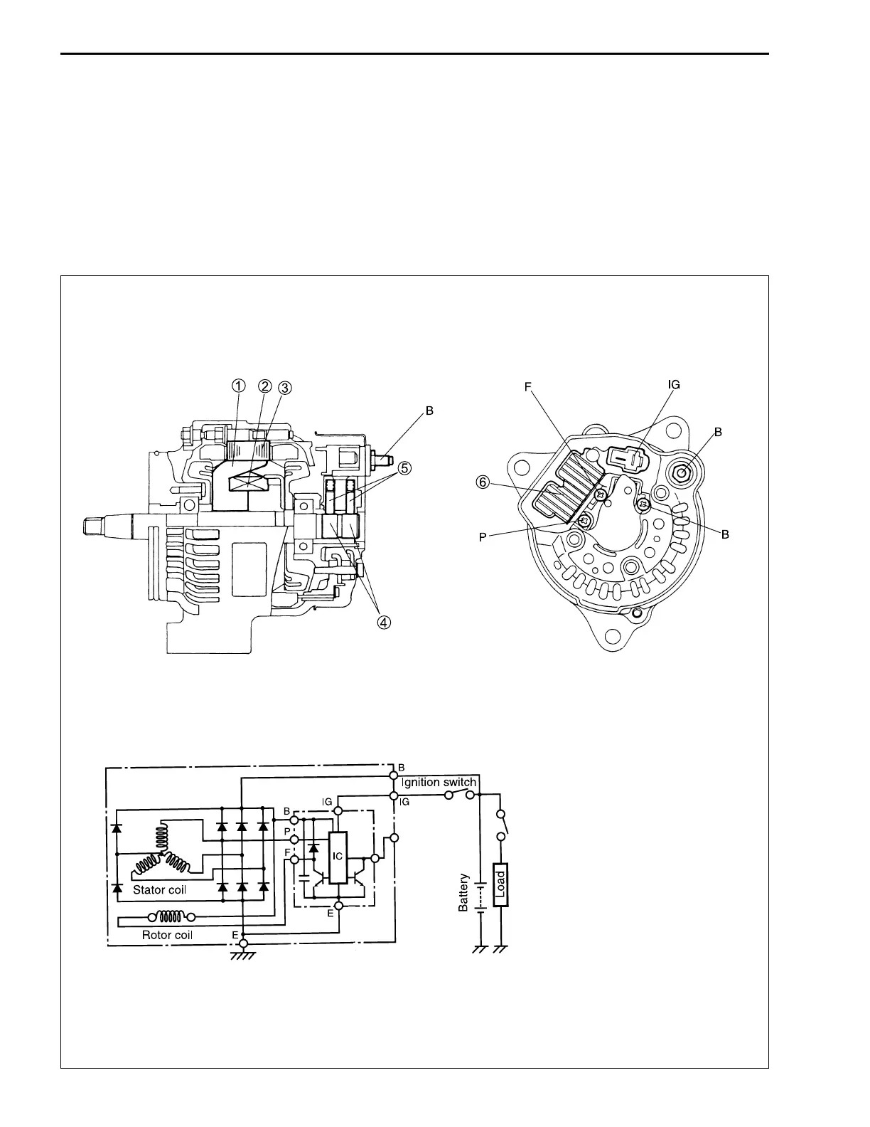
If the battery of your Suzuki Motorcycle runs down quickly, start by checking the battery for current leaks. Also, measure the charging voltage at the battery terminals, the continuity of the stator coil and rotor coil, and inspect the slip rings, rectifier and IC. Inspect the wires, as poor contact of couplers could be the cause. The battery itself might also be faulty.


