Engine General Information and Diagnosis: 1A-50
C21 (Use of mode select switch)
Step Action Yes No
1 1) Remove the left side cover. Refer to “Front Side Exterior
Parts Removal and Installation in Section 9D (Page 9D-
6)”.
2) Turn the ignition switch OFF.
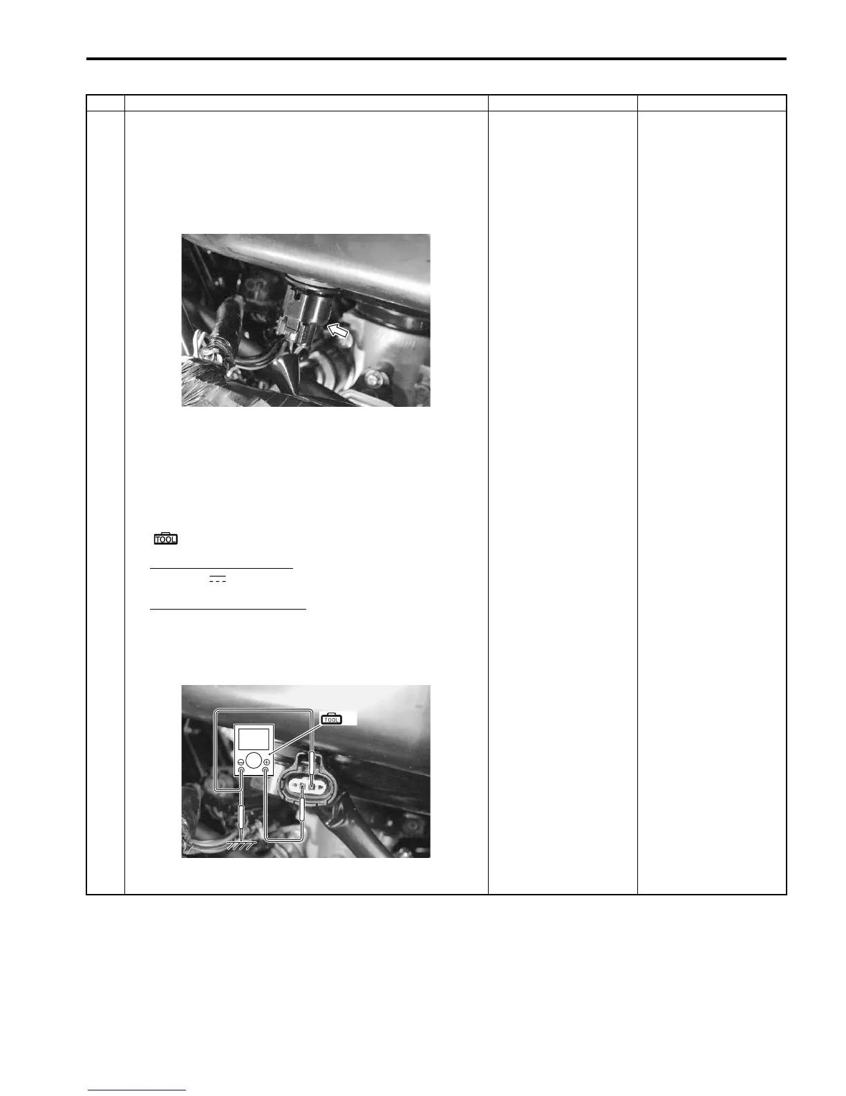
3) Check the IAT sensor coupler for loose or poor contacts.
If OK, then measure the IAT sensor voltage.
4) Disconnect the coupler and turn the ignition switch ON.
5) Measure the voltage between the Dg wire terminal and
ground.
If OK, then measure the input voltage between Dg wire
terminal and B/Br wire terminal.
Special tool
(A): 09900–25008 (Multi-circuit tester set)
Tester knob indication
Voltage ( )
IAT sensor input voltage
4.5 – 5.5 V
((+) terminal: Dg – (–) terminal: Ground, (+) terminal:
Dg – (–) terminal: B/Br)
Is the voltage OK?
Go to Step 2. • Loose or poor
contacts on the ECM
coupler.
• Open or short circuit
in the Dg wire or B/Br
wire.
I831G1110051-01
(A)
V
I831G1110052-02

 Loading...


