Steering / Handlebar: 6B-4
8) Remove the following parts from the right handlebar.
a) Right grip (4)
b) Front brake master cylinder/Front brake lever (5)
CAUTION
!
Do not turn the front brake master cylinder
upside down.
c) Throttle lever case (6)
9) Remove the handlebar upper clamps (7) and
handlebars (8).
Installation
Install the handlebars in the reverse order of removal.
Pay attention to the following points:
• Install the washers (1) and bolts (2) as shown in the
steering/handlebars construction. Refer to “Steering /
Handlebars Assembly Construction (Page 6B-2)”.
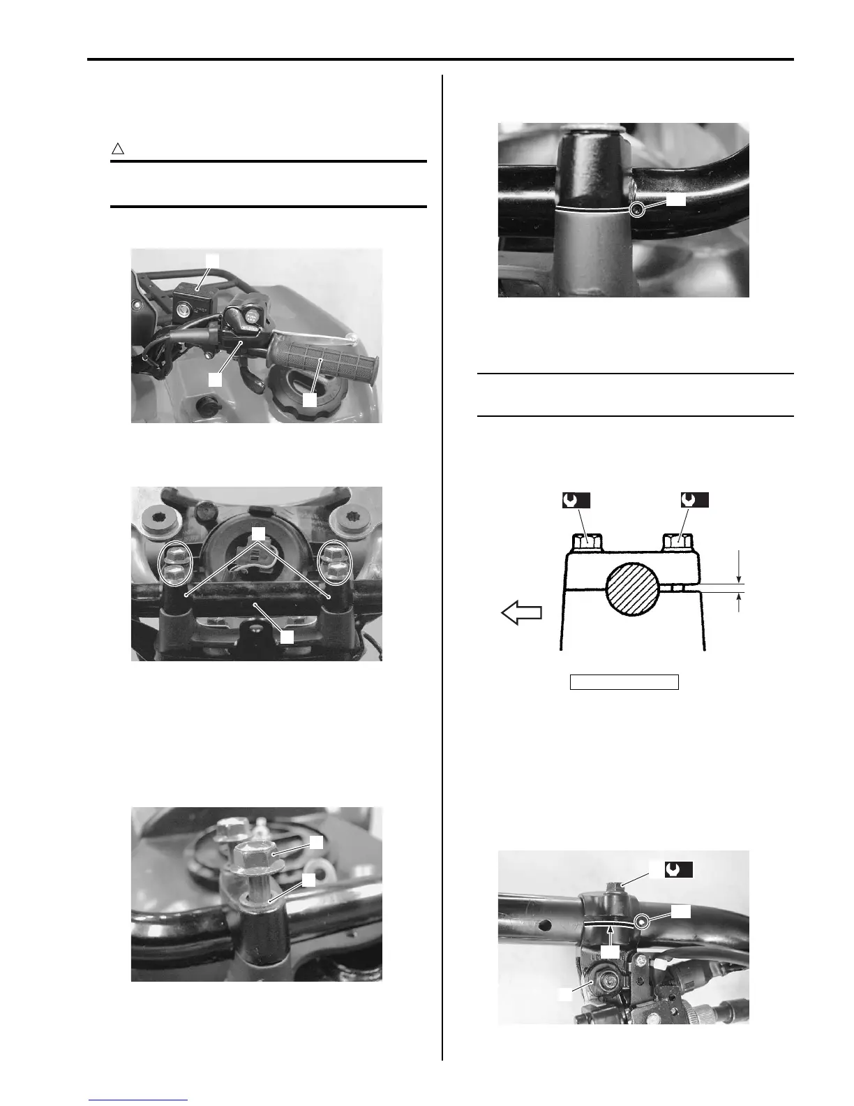
• Set the handlebars so that its punch mark “A” aligns
with the mating surface of the left handlebar holder.
• Tighten the handlebar holder bolts (3) to the specified
torque.
NOTE
First tighten the handlebar holder bolts (3)
(front ones) to the specified torque.
Tightening torque
Handlebar clamp bolt (a): 26 N·m (2.6 kgf-m, 19.0
lb-ft)
• Align the punch mark “A” on the handlebars with the
mating surface “B” of rear brake lever assembly.
• Tighten the rear brake lever holder clamp bolt (4) to
the specified torque.
Tightening torque
Rear brake lever holder clamp bolt (b): 11 N·m (
1.1 kgf-m, 8.0 lb-ft)
4
5
6
I831G1620009-01
7
8
I831G1620010-01
1
2
I831G1620011-01
“a”: Clearance
“A”
I831G1620012-02
“a”
(a)
3
(a)
FWD
I831G1620013-01
“A”
“B”
(b)
4
3
I831G1620049-01

 Loading...


