Engine General Information and Diagnosis: 1A-2
Compensation of Injection Time (Volume)
The following different signals are output from the respective sensors for compensation of the fuel injection time
(volume).
Injection Stop Control
Self-Diagnosis Function
The self-diagnosis function is incorporated in the ECM. The function has two modes, “User mode” and “Dealer mode”.
The user can only be notified by the LCD (DISPLAY) panel and LED (FI indicator light). To check the function of the
individual FI system devices, the dealer mode is prepared. In this check, the special tool is necessary to read the code
of the malfunction items.
User Mode
*1
Current letter displayed any one of the clock/hour meter.
*2
When one of the signals is not received by ECM, the fail-safe circuit works and injection is not stopped. In this case,
“FI” and clock/hour meter (*1) are indicated in the LCD panel and vehicle can run.
*3
The injection signal is stopped, when the crankshaft position sensor signal, tip-over sensor signal, ignition signal,
injector signal, fuel pump relay signal or ignition switch signal is not sent to ECM. In this case, “FI” is indicated in the
LCD panel. Vehicle does not run.
“CHEC”:
The LCD panel indications “CHEC” when no communication signal from the ECM is received for 3 seconds.
For Example:
The ignition switch is turned ON, and the engine stop switch is turned OFF. In this case, the speedometer does not
receive any signal form ECM, and the panel indicates “CHEC”.
Signal Descriptions
ENGINE COOLANT TEMPERATURE SENSOR
SIGNAL
When engine coolant temperature is low, injection time (volume)
is increased.
INTAKE AIR TEMPERATURE SENSOR SIGNAL
When intake air temperature is low, injection time (volume) is
increased.
BATTERY VOLTAGE SIGNAL
ECM operates on the battery voltage and at the same time, it
monitors the voltage signal for compensation of the fuel injection
time (volume). A longer injection time is needed to adjust injection
volume in the case of low voltage.
ENGINE RPM SIGNAL At high speed, the injection time (volume) is increased.
STARTING SIGNAL
When starting engine, additional fuel is injected during cranking
engine.
ACCELERATION SIGNAL/ DECELERATION
SIGNAL
During acceleration, the fuel injection time (volume) is increased
in accordance with the throttle opening speed and engine rpm.
During deceleration, the fuel injection time (volume) is decreased.
Signal Descriptions
TIP-OVER SENSOR SIGNAL (FUEL SHUT-OFF)
When the vehicle tips over, the tip-over sensor sends a signal to
the ECM. Then, this signal cuts OFF current supplied to the fuel
pump, fuel injectors and ignition coils.
OVER-REV. LIMITER SIGNAL
The fuel injector stops operation when engine rpm reaches rev.
limit rpm.
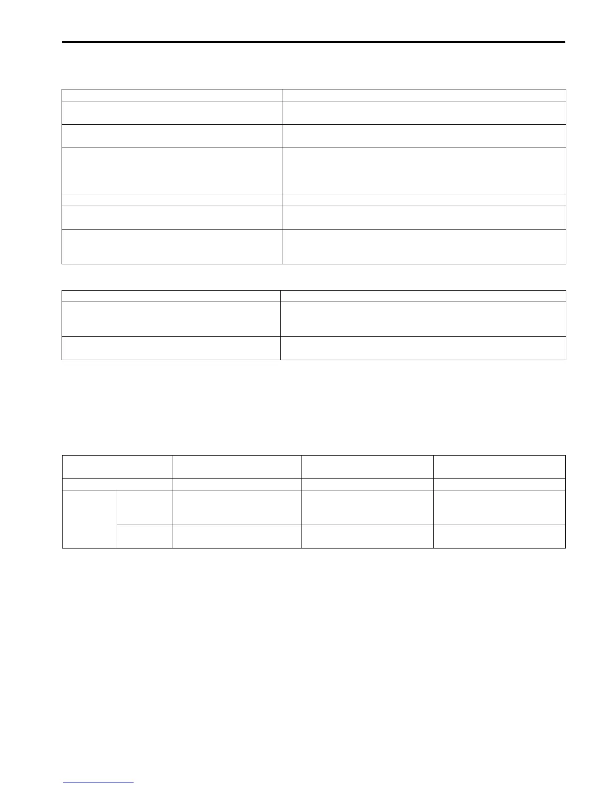
Malfunction
LCD (display) indication
“A”
FI indicator light indication
“B”
Indication mode
“NO” Clock/Hour meter *1 — —
“YES”
Engine can
start
Clock/Hour meter (*1) and
“FI” letters *2
FI indicator light turns ON.
Each 2 sec. Odometer (*1)
and “FI” is indicated
alternately.
Engine can
not start
“FI” letters *3
FI indicator light turns ON and
blinks.
“FI” is indicated continuously.

 Loading...


