60
Operation and maintenance instructions
TAC control board
ALARM OUTPUT AL dPa OUTPUT LED ALARM Fans
/ / ON /
Auto reset: yes
- Diagnostic:
• Check in TACtouch the screen with the communication
sensor errors in menu/info: the Modbus pressure sensor
which is in alarm will have its error counter that increases
(if the screen doesn’t appear, go rst in menu settings/
Factory setup). Once identify, check rst of all that it
is well present otherwise, it will be necessary to modify
the conguration to tell the control board that it is not
present.
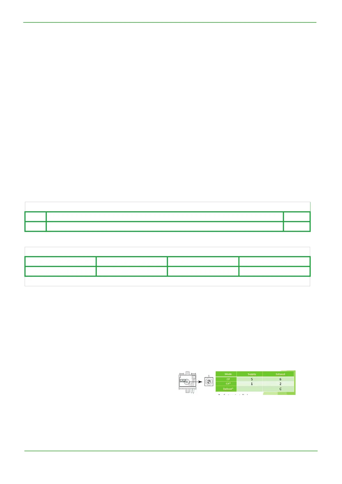
• If the sensor is well present, check that the address of the
wheel is correct.
• Finally, check it’s status led: green led on, communication
orange blinking. If status led are dierent, then it may
be due to the cable or to sensor itself that is damaged.
Wiring is in chain from connector RJ3 or RJ4 for sensors 1
(kit CA supply), 2 (kit CA exhaust) and C (defrost), from
connector RJ2 for sensor 5 (CP mode supply) and 6 (CP
mode exhaust). See TAC wiring overview at point 4:
- Conditions:
• Unit with at least one congured Modbus pressure sensor.
- Causes:
•
One or more of the Modbus pressure sensors give too much communication errors.
This in turn can come from:
The physical absence of one of the congured sensor.
One of the sensors is not powered on: check “ON” led of all congured sensors. See installation manual of Modbus
pressure sensor.
Faulty cable
One of the sensors address is not correctly set: check the setting wheel position for each congured sensor according to
its function. See diagnostic here below.
.
- Eects:
8.22 TYPE 21: ALARM INDICATING COMMUNICATION ERROR FOR ONE OF THE MODBUS
PRESSURE SENSOR
Displayed on HMI TACtouch
Code Text displayed Level
D.30 MODBUS SENSOR COMMUNICATION ERROR 1
 Loading...