47
FIRE DAMPER - FD
PRODUCT OVERVIEW
DIMENSIONS
INSTALLATIONS
ACTUATORS
ACCESSORIES
REPLACEMENTS
MAINTENANCE AND OPERATION
MANUAL
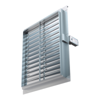
ACTUATORS
R, R-S
Manual operating mechanism, optionally with end
switches (R-S). In case of fire, the fire damper closes
automatically. Damper closing can be initiated either
by thermal fuse melting, or by manual activation on the
operating mechanism. Upon closure, damper blade
is locked in closed position and can only be opened
manually. Thermal fuse melting point is 72 °C.
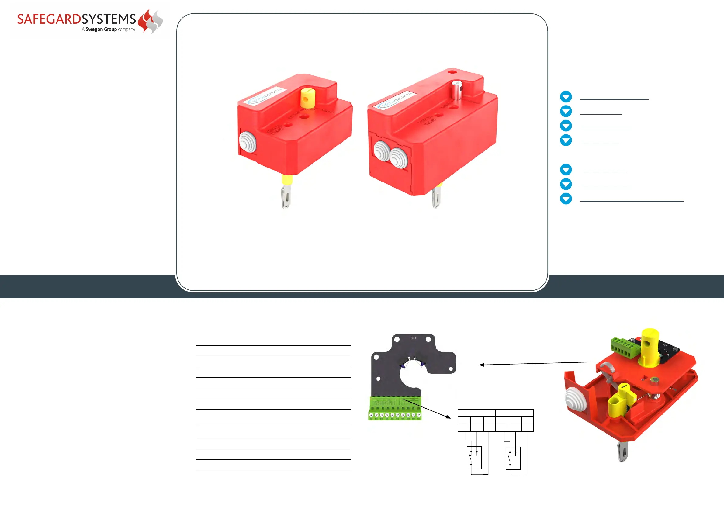
Wiring diagramTechnical specifications
Nominal voltage N/A
Power N/A
Switching capacity 1mA…500mA, 5VDC…48VDC
Blade closing time Spring: 1 sec
Blade opening time Manual
Manual activation Release button on the casing
Degree of protection IP 42
Ambient temperature
range
min. -30 °C, max. 50 °C
Ambient humidity
95% r.h.,
non-condensing
Service life Min. 30,000 cycles
Maintenance Maintenance-free
Weight R25/R40
0,5 kg / 1,7 kg
R25
(up to 800x600)
R40
(800x600 up to1500x800)
FC = Limit switch - end
DC = Limit switch - start
NO = normally open
NF = normally closed
C = common
FC
DC
NF
NO
C
NF
NO
C
11 12 13 14 15 1 6
R25
R25 manual actuator is installed on FD25 fi
re
dampers range fr
om 100x200 till 800x600. It is
available in version with (R-S) and without (R) end
switches. End switches and thermal fuse ar
e easily
replaceable and available as service parts.
R40
R40 manual actuator is installed on FD40 fire
dampers from 800x600 till 1500x800. It is
available in version with (R-S) and without (R) end
switches. End switches, thermal fuse are easily
replaceable and available as service parts.
ACTUATORS
 Loading...