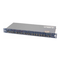
528E
20
Using the 528E Chapter 7
This section is intended for more advanced users. If you are a fi rst-time user, we recommend that
you start out by using the procedure found in “Fast Setup.”
Block Diagram
Figure 7-1 on the next page is the block diagram for the 528E. Please take a moment and take note
of the fol low ing:
• The equalizer and de-esser are hard-wire bypassed by their IN/OUT switch es.
• The interstage patch points use TRS jacks wired for unbalanced operation.
• The interstage patch points are half-normalled. The send jack does not break the signal fl ow.
The output level of the 528E can be set to either line level or mic level. The switch for this function
is internal to the unit. Refer to Appendix A.
Installation
The 528E may be installed freestanding or rack mounted. Rubber feet are included for freestanding
use. No special ventilation requirements are necessary. Table 7-1 lists the 528E’s re quire ments for
installation.
Installation Requirements
Mechanical One rack space (1.75 inches) required, 12.5 inches depth (including con nec tor
allowance). Rear chassis support recommended for road applications.
Electrical 105-125V ac, 12.5 Watts maximum. 210-250V ac, 50 Hz, 12.5W maximum
(export).
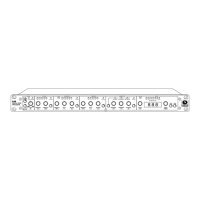
Connectors XLR-3 female for inputs, XLR-3 male and TRS 1/4-inch female for outputs, Pin
2 of the XLR connectors is “Hot.”
The sidechain access jack output uses a TRS jack wired as an insert jack (tip=return, ring=send).
The interstage patch points use TRS jacks with the ring and sleeve connections connected to circuit
ground. The jacks are half-normalled (only input breaks normal).
Level Setting
For optimum noise performance, correct level settings are a must, especially for microphone
sources. You should operate the 528E’s mic preamp at the highest gain possible without overload.
Extremely hot signals may require using the -15 dB pad switch.
The 528E expects line level signals to fall in the +4 dBu region. Lower signal levels are okay, but
the noise performance may suffer as there is no gain trim control for the line input.
The C
LIP LED in the mic input section of the 528E actually monitors the output of the MIC-LINE
switch. If the LED glows, and you are using the MIC input, then reduce the setting of the MIC GAIN
control until the LED no longer glows. If you are using the LINE input, reduce the level of the de-
vice driving the 528E.
The C
LIP LED in the OUTPUT LED meter monitors levels in the equalizer as well as at the output
of the 528E. If the CLIP LED glows, try switching the equalizer to BYPASS. If the LED still glows,
reduce the setting of the OUTPUT GAIN control. If switching the equalizer to BYPASS eliminates the
clip indication, then the input level must be reduced via the MIC GAIN control or by lowering the
level of the line input.