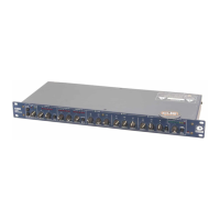
528E
32
This section discusses a multitude of things, all related to getting signals in and out of the 528E.
Matching Levels vs Matching Impedances
In any audio equipment application, the question of “matching” inevitably comes up. Without dig-
ging a hole any deeper than absolutely necessary, we offer the following discussion to (hope ful ly)
clarify your understanding of the subject.
Over the years, we have all had impedance matching pounded into our heads. This is important
only for ancient audio systems, power amplifi ers, and RF. Technically speaking, the reason is power
transfer, which reaches a maximum when source and load are matched. Modern audio systems are
voltage transmission systems and source and load matching is not only unnecessary, but undesir-
able as well.
• Ancient audio systems operate at 600 ohms (or some other impedance value), and must be
matched, both at their inputs and at their outputs. Generally speaking, if you are dealing with
equipment that uses vacuum tubes, or was designed prior to 1970, you should be concerned
about matching. These units were designed when audio systems were based on maximum
power transfer, hence the need for input/output matching.
• Power amplifi ers are fussy because an abnormally low load impedance generally means a visit
to the amp hospital. Thus, it’s important to know what the total impedance of the pile of
speakers connected to the amplifi er really is.
• RF systems are matched because we really are concerned with maximum power transfer and
with matching the impedance of the transmission line (keeps nasty things from happening).
Video signals (composite, baseband, or otherwise) should be treated like RF.
Some folks seem to believe that balanced/unbalanced lines and impedances are related; or even
worse that they are associated with a particular type of connector. Not so. Unbalanced signals are
not necessarily high-impedance and balanced signals/lines are not necessarily low-impedance.
Similarly, although 1/4-inch jacks are typically used for things like guitars (which are high-im ped -
ance and unbalanced), this does not predispose them to only this usage. After all, 1/4 inch jacks are
sometimes used for loudspeakers, which are anything but high-impedance. Therefore, the presence
of 3-pin XLR connectors should not be construed to mean that the input or output is low-impedance
(or high-impedance). The same applies to 1/4-inch jacks.
So, what is really important? Signal level, and (to a much lesser degree), the impedance relation
between an output (signal source) and the input that it connects to (signal receiver).
Signal level is very important. Mismatch causes either loss of headroom or loss of signal-to-noise
ratio. Thus, microphone inputs should only see signals originating from a microphone, a direct
(DI) box, or an output designated microphone-level output. Electrically, this is in the range of ap-
prox i mate ly -70 to -20 dBm. Line inputs should only see signals in the -10 to +24 dBm/dBu range.
Guitars, high-impedance microphones, and many electronic keyboards do not qualify as line-level
sources.
The impedance relation between outputs and inputs needs to be considered, but only in the follow-
ing way:
Always make sure that a device’s input impedance is higher than the output source impedance of
the device that drives it.
Some manufacturers state a relatively high-impedance fi gure as the output impedance of their
equip ment. What they really mean is that this is the minimum load impedance that they would like
their gear to see. In most cases, seeing a output impedance fi gure of 10,000 (10K) ohms or higher
from modern equipment that requires power (batteries or AC) is an instance of this type of rating.
If so, then the input impedance of the succeeding input must be equal to or greater than the output
impedance of the driving device.
Symetrix equipment inputs are designed to bridge (be greater than 10 times the actual source im-
ped ance) the output of whatever device drives the input. Symetrix equipment outputs are designed
Chapter 9Technical Tutorial