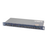
528E
33
to drive 600-ohm or higher loads (600-ohm loads are an archaic practice that won’t go away). You
don’t need to terminate the output with a 600-ohm resistor if you aren’t driving a 600-ohm load. If
you don’t un der stand the concept of termination, you probably don’t need to anyway.
The two facts that you need to derive from this discussion are:
1. Match signal levels for best headroom and signal-to-noise ratio.
2. For audio, impedance matching is only needed for antique equipment and power amplifi er
outputs. In all other cases, ensure that your inputs bridge (are in the range of 2 to 200 times the
output source impedance) your outputs.
Signal Levels
The 528E is designed around studio/pro fes sion al line levels: +4 dBu or 1.23 volts. The unit is quiet
enough to operate at lower signal levels such as those found in semi-pro or musical-instrument (MI)
equipment (-10 dBu or 300 millivolts).
The microphone input is designed to accept low-impedance microphones. Switchable 48V phan tom
powering is provided for suitable condenser microphones. The microphone input accepts signal
levels from -60 to -5 dBV (+10 dBV with the -15 dB pad).
The line input is designed to accept nominal line level: +4 dBu.
The output line driver delivers +4 dBm into 600-ohm or higher balanced loads. An internal switch
converts the line level output to microphone level, or -36 dBu. An unbalanced output is also avail-
able via a 1/4" TRS phone jack. This jack is always line-level and is unaffected by the internal
switch.
I/O Impedances
The 528E is designed to interface into almost any recording studio or sound reinforcement ap pli -
ca tion. This includes:
• 600 ohm systems where input and output impedances are matched.
• Unbalanced semi-professional equipment applications.
• Modern bridging systems where inputs bridge and outputs are low source impedances
(voltage transmission systems).
The 528E’s microphone input is intended to bridge a 150-ohm balanced source. The actual input
impedance is approximately 8-kilohms. 48V phantom powering for condenser microphones is pres-
ent if the PHANTOM POWER switch has been depressed. Refer to the discussion of phantom powering
on the next page for ad di tion al in for ma tion.
The 528E’s line input impedance is 10-kilohms balanced, and 10-kilohms unbalanced. The inputs
may be driven from any source (balanced or unbalanced) capable of delivering at least -10 dBu into
the aforementioned impedances.
The 528E’s output impedance is 200 ohms balanced, 100 ohms unbalanced. The output line driver
delivers +18 dBm into a 600-ohm balanced load or +18 dBm into 600-ohm unbalanced loads.
Polarity Convention
The 528E uses the international standard polarity convention of pin 2 hot. Therefore:
XLR Tip-Ring-Sleeve Signal
1 Sleeve Ground
2 Tip High
3 Ring Low
If your system uses balanced inputs and outputs, and uses the 528E this way, then the polarity con-
vention is unimportant. If your system is both balanced and unbalanced, then you must pay atten-
tion to this, especially when going in and coming out through different connector types (like input
on an XLR, output on a phone jack).